Removal Procedure
Important: Do not raise the engine block by the crankshaft
balancer to perform this service procedure. Damage to the crankshaft balancer or
the crankshaft may occur.
- Disconnect both the battery negative
cables from the batteries. Refer to
Battery Cable
in Engine Electrical.
- Remove the oil level indicator and tube from the engine. Refer to
Oil Level Indicator and Tube Replacement
.
- Raise the vehicle.
- Support the vehicle with safety stands.
- Drain the engine oil.
- Remove the transmission (2 wheel drive models only) from the vehicle.
- Remove the clutch assembly (if equipped). Refer to
Clutch Assembly Replacement
in Clutch.
- Remove the front propeller shaft (4 wheel drive models only). Refer to
Front Propeller Shaft Replacement
in Driveline/Axle.
- Remove the front differential carrier from the vehicle. Refer to
Differential Carrier Assembly Replacement
in Front Axle.
- Remove the flywheel from the crankshaft. Refer to
Engine Flywheel Replacement
.
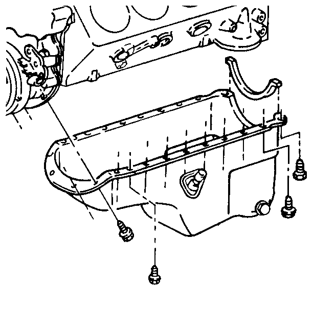
- Remove the oil pan bolts from the oil pan.
- Using a block of wood and a hammer, tap the side of the oil pan until
seal is broken.
- Remove the oil pan from the engine block.
- Remove
the rear seal on the from the oil pan.
- Clean the old RTV sealant from the oil pan and engine block.
- Clean all the oil and grease from the sealing surfaces.
Installation Procedure
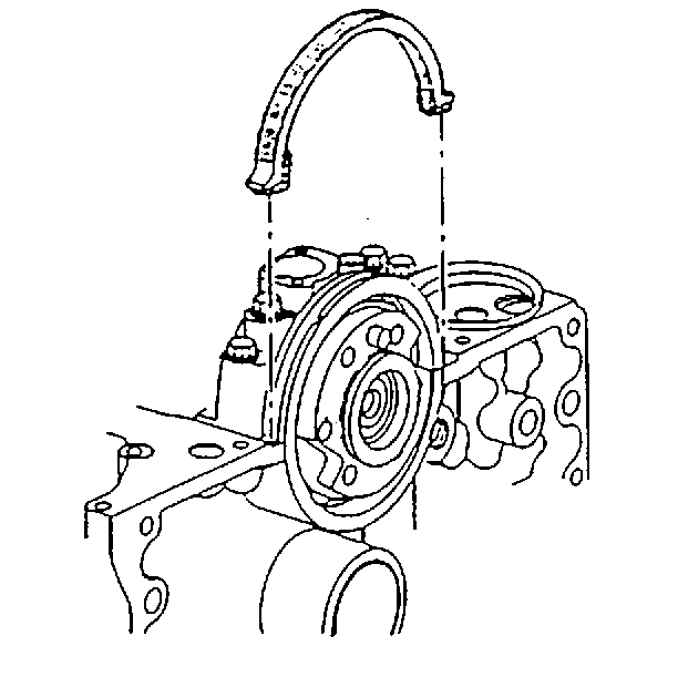
- Apply
a 2 mm (1/16 inch) bead of RTV sealant GM P/N 12345739 to the oil pan rear
seal at the inside corners where the seal meets the rear crankshaft bearing cap
on the engine block.
- Install the oil pan rear seal to the rear crankshaft bearing cap before
the sealer starts to dry.
- Install the oil pan to the engine
block.
Notice: Use the correct fastener in the correct location. Replacement fasteners
must be the correct part number for that application. Fasteners requiring
replacement or fasteners requiring the use of thread locking compound or sealant
are identified in the service procedure. Do not use paints, lubricants, or
corrosion inhibitors on fasteners or fastener joint surfaces unless specified.
These coatings affect fastener torque and joint clamping force and may damage
the fastener. Use the correct tightening sequence and specifications when
installing fasteners in order to avoid damage to parts and systems.
- Install the oil pan bolts to the engine block.
Tighten
- Tighten the bolts in the following order:
- Tighten the two rear bolts to 17 N·m (23 lb ft).
- Tighten all the other bolts to 10 N·m (89 lb in).
- Install the flywheel to the crankshaft. Refer to
Engine Flywheel Replacement
.
- Install the clutch assembly (if equipped). Refer to
Clutch Assembly Replacement
in Clutch.
- Install the transmission (2 wheel drive models only) to the vehicle.
- Install the front differential carrier in the vehicle (4 wheel drive
models only). Refer to
Differential Carrier Assembly Replacement
in Front Axle.
- Install the front propeller shaft (4 wheel drive models only). Refer
to
Front Propeller Shaft Replacement
in Driveline/Axle.
- Lower the vehicle.
- Install the oil level indictor and tube to the engine block. Refer to
Oil Level Indicator and Tube Replacement
.
- Fill the crankcase with engine oil.
- Connect both the battery negative cables to the batteries. Refer to
Battery Cable
in Engine Electrical.
