Engine Mount Replacement Left Side
Removal Procedure
Important: When performing this service procedure, do not lift the engine block by the crankshaft balancer. Damage to the crankshaft balancer, crankshaft pulleys, or the crankshaft could occur.
Do not replace the left or right at the same time. They must be replaced in two separate service procedures, so as not to cause an alignment problem when re-installing the engine mounts.- Disconnect both the battery negative cables from the batteries. Refer to Battery Cable in Engine Electrical.
- Raise the vehicle and support with safety stands.
- Move the front wheel to the left against the steering stops.
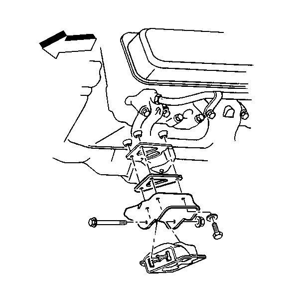
- Install the pole jack on the engine locating tab just to the left rear of the power steering pump.
- If servicing a 2 wheel drive vehicle, remove the engine mount assembly bolts, nuts, and washers.
- Remove the engine mount assembly.
- Remove the engine mount through bolt and the nut.
- Raise the engine only enough to permit removal of the engine mount.
- If servicing a 4 wheel drive vehicle, remove the engine mount assembly bolts, nuts, and washers.
- Remove the engine mount assembly.
Installation Procedure
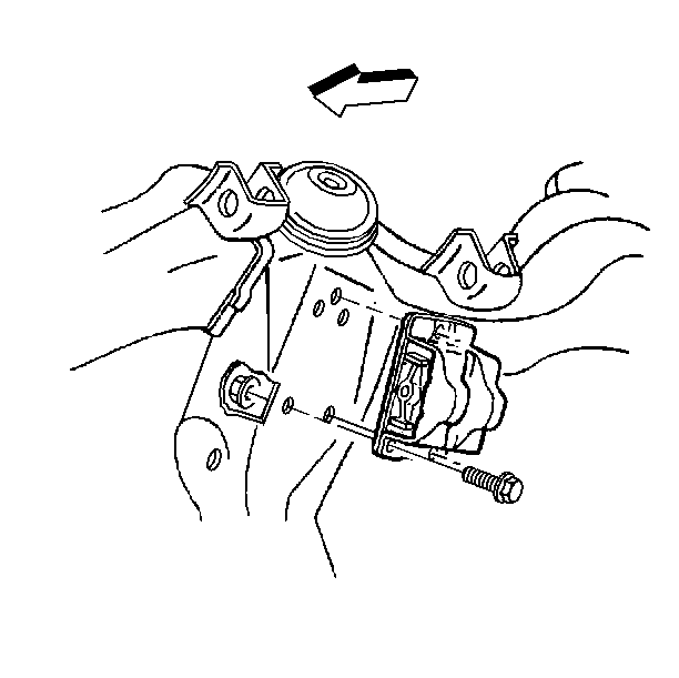
- If servicing a 2 wheel drive vehicle, install the engine mount assembly.
- Install the engine mount assembly bolts, nuts, and washers.
- If servicing a 4 wheel drive vehicle, install the engine mount assembly.
- Lower the engine until the engine mount through bolt can be inserted.
- Install the engine mount through bolt and the nut.
- Remove the pole jack from the vehicle.
- Connect both the battery negative cables to the batteries. Refer to Battery Cable in Engine Electrical.
Notice: Use the correct fastener in the correct location. Replacement fasteners must be the correct part number for that application. Fasteners requiring replacement or fasteners requiring the use of thread locking compound or sealant are identified in the service procedure. Do not use paints, lubricants, or corrosion inhibitors on fasteners or fastener joint surfaces unless specified. These coatings affect fastener torque and joint clamping force and may damage the fastener. Use the correct tightening sequence and specifications when installing fasteners in order to avoid damage to parts and systems.
Tighten
| • | Tighten the bolts to 59 N·m (44 lb ft). |
| • | Tighten the nuts to 45 N·m (33 lb ft). |
Tighten
| • | Tighten the bolts to 59 N·m (44 lb ft). |
| • | Tighten the nuts to 45N·m (33 lb ft). |
Tighten
Tighten the through bolt nut to 68 N·m (50 lb ft).
Engine Mount Replacement Right Side
Removal Procedure
- Disconnect both the battery negative cable from the batteries. Refer to Battery Cable in Engine Electrical.
- Raise the vehicle and support with safety stands.
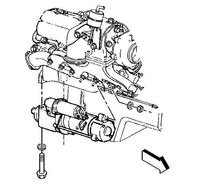
- Remove the starter from the engine block (right side only) and secure out of the way. Refer to Starter Motor Replacement in Engine Electrical.
- Install a pole jack on the right rear corner of the engine block just above starter.
- Remove the engine mount through bolt and the nut.
- Raise the engine only enough to permit removal of the engine mount.
- If servicing a 2 wheel drive vehicle, remove the engine mount assembly bolts, nuts, and washers.
- Remove the engine mount assembly.
- If servicing a 4 wheel drive vehicle, remove the engine mount assembly bolts, nuts, and washers.
- Remove the engine mount assembly.
Installation Procedure
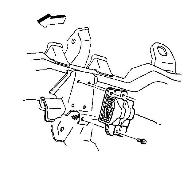
- If servicing a 2 wheel drive vehicle, install the engine mount assembly.
- Install the engine mount assembly bolts, nuts, and washers to the crossmember.
- If servicing a 4 wheel drive vehicle, install the engine mount assembly.
- Install the engine mount nuts, bolts, and washers to the crossmember.
- Remove the pole jack from the engine block.
- Install the starter to the engine block (right side only). Refer to Starter Motor Replacement in Engine Electrical.
- Lower the engine until the engine mount through bolt can be inserted.
- Install the engine mount through bolt and the nut.
- Connect both the battery negative cables to the batteries. Refer to Battery Cable in Engine Electrical.
Notice: Use the correct fastener in the correct location. Replacement fasteners must be the correct part number for that application. Fasteners requiring replacement or fasteners requiring the use of thread locking compound or sealant are identified in the service procedure. Do not use paints, lubricants, or corrosion inhibitors on fasteners or fastener joint surfaces unless specified. These coatings affect fastener torque and joint clamping force and may damage the fastener. Use the correct tightening sequence and specifications when installing fasteners in order to avoid damage to parts and systems.
Tighten
| • | Tighten the bolts to 59 N·m (44 lb ft). |
| • | Tighten the nuts to 45 N·m (33 lb ft). |
Tighten
| • | Tighten the bolts to 59 N·m (44 lb ft). |
| • | Tighten the nuts to 45 N·m (33 lb ft). |
Tighten
Tighten the through bolt nut to 68 N·m (50 lb ft).
