Removal Procedure
- Disconnect negative battery cable. Refer to Battery Negative Cable Disconnection and Connection in Engine Electrical.
- Remove the air intake duct between the air cleaner and the turbocharger inlet housing.
- Drain the cooling system. Refer to Cooling System Draining and Filling .
- Remove the upper fan shroud. Refer to Engine Coolant Fan Upper Shroud Replacement in Engine Cooling.
- Remove the fan. Refer to Fan Replacement in Engine Cooling.
- Remove the drive belt. Refer to Drive Belt Replacement in Engine Mechanical - 6.6L.
- Remove the bolt holding the positive battery cable junction box and bracket and move out of the way.
- Remove the A/C compressor. Refer to Air Conditioning Compressor Replacement in HVAC.
- Remove the power steering pump. Refer to Power Steering Pump Replacement in Power Steering Systems.
- Position the A/C compressor and power steering pump aside.
- Remove the oil filler tube. Refer to Oil Filler Tube Replacement in Engine Mechanical - 6.6L.
- Remove the air conditioning/power steering bracket.
- Remove the generator. Refer to Generator Replacement in Engine Mechanical - 6.6L.
- Remove the thermostat housing bracket, wiring and fuel test port, and two nuts.
- Remove the positive crankcase ventilation (PCV) catch tank from the PCV bracket and bolt below holding lower line, and move to the side.
- Remove the generator bracket. Refer to Generator Bracket Replacement in Engine Electrical.
- Remove the turbo cooling hose return line clamp and hose.
- Remove the upper radiator hose at the outlet pipe. Remove the bracket and support the bracket at the valve cover, and swing out of the way.
- Remove bolt holding wiring support bracket at thermostat housing.
- Move the main wiring harness by disconnecting the following:
- Flip the wire harness and harness tray towards the back and set aside.
- Disconnect the heater pipe bolt and temperature sensor wire from the thermostat housing.
- Remove the air intake pipe. Refer to Air Intake Pipe Replacement .
- Remove the thermostat housing crossover. Refer to Thermostat Housing Crossover Replacement in Engine Cooling.
- Remove the hose to the turbo water feed line. Refer to Turbocharger Coolant Hoses/Pipes Replacement in Engine Cooling.
- Disconnect all high pressure fuel lines and remove supply pipe and hose at the fuel injection pump and function block. Refer to Metal Collar Quick Connect Fitting Service .
- Remove the supply hose from the fuel injection pump.
- Remove the fuel return hose from fuel injection pump.
- Remove the high pressure line from the injection pump to the junction block.
- Remove fuel injection pump from the block using two screwdrivers to work the pump from the block towards rear of engine keeping the pump straight.
- Remove fuel injection pump.
Important: Cover the air intake pipe end with duct tape to prevent the infiltration of dirt.
Important: Remove only the air conditioning/power steering bracket. Do not discharge the A/C or remove the A/C and power steering lines.
| • | The fuel pressure regulator connector on the fuel injection pump |
| • | The fuel injection control module connectors |
Important: Cap all of the open fuel connections with suitable plastic plugs in order to prevent infiltration of dirt.
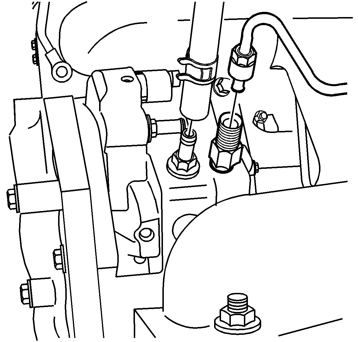
Important: Be careful not to damage any mating surfaces.
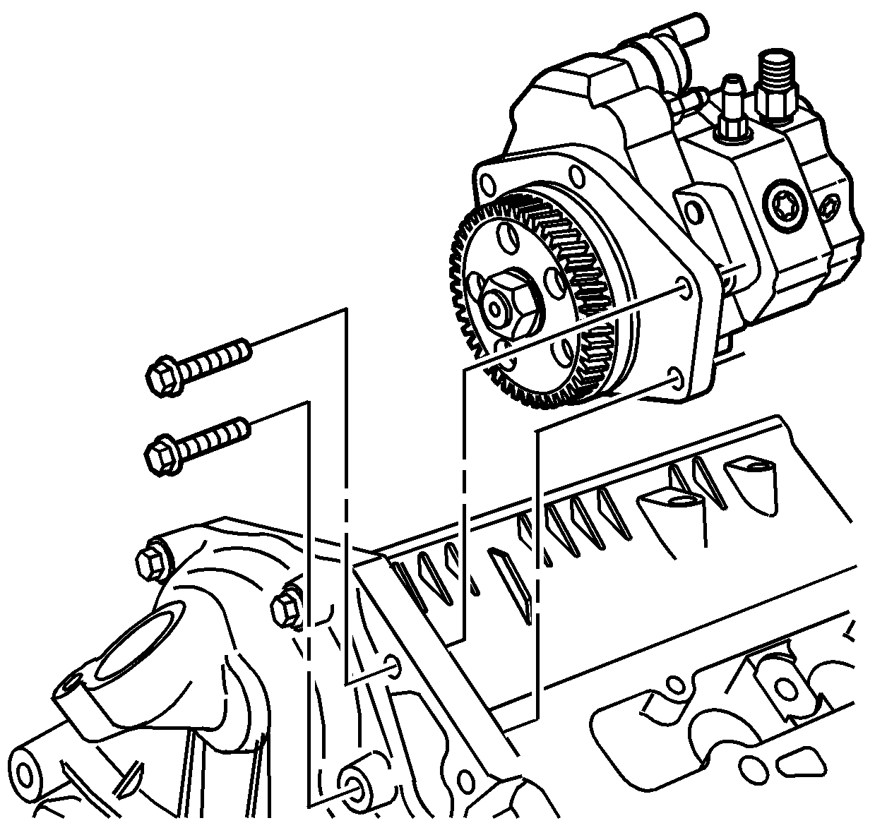
Preparing The Fuel Pump
- Hold the fuel pump by the drive gear in a vice with copper jaw liners.
- Loosen the gear nut until the nut is even with the end of the gear shaft.
- Remove the gear from the tapered shaft of the pump.
- Separate the pump and adapter by removing the three bolts and spacers.
- Inspect the O-ring for damage on pump adapter and replace, if necessary. Lubricate the O-ring with clean engine oil.
- Clean all mating surfaces.
- Install the adapter on the pump.
- Using the three bolts and spacers, reassemble the pump.
- Install the gear and nut.
Notice: Use the correct fastener in the correct location. Replacement fasteners must be the correct part number for that application. Fasteners requiring replacement or fasteners requiring the use of thread locking compound or sealant are identified in the service procedure. Do not use paints, lubricants, or corrosion inhibitors on fasteners or fastener joint surfaces unless specified. These coatings affect fastener torque and joint clamping force and may damage the fastener. Use the correct tightening sequence and specifications when installing fasteners in order to avoid damage to parts and systems.
Tighten
Tighten the bolts to 20 N·m (15 lb ft).
Tighten
Tighten nut to 70 N·m (52 lb ft).
Installation Procedure
- Install the fuel injection pump.
- Install the fuel injection pump bolts to the front of the engine front cover.
- Connect the fuel return line banjo bolt at the junction block.
- Install the fuel supply hose and hose clamp to the fuel injection pump.
- Install fuel return hose and hose clamp to the fuel injection pump.
- Install high pressure lines to the injection pump to the junction block.
- Install the fuel pressure sensor connector at the junction block.
- Replace the hose to turbocharger water feed line. Refer to Turbocharger Coolant Hoses/Pipes Replacement in Engine Cooling.
- Install the thermostat housing crossover. Refer to Thermostat Housing Crossover Replacement in Engine Cooling.
- Install air intake pipe. Refer to Air Intake Pipe Replacement .
- Install the heater pipe using the following procedure:
- Connect the engine wiring harness.
- Install upper radiator hose at outlet pipe using the following procedure:
- Install turbo cooling hose return and clamp.
- Install the left idler pulley and bolt.
- Install PCV catch tank, hose clamp and bolt to the right front of the engine.
- Install the thermostat housing bracket, wiring, fuel test port and nuts.
- Install the generator. Refer to Generator Replacement in Engine Electrical.
- Install a new O-ring to the oil fill tube and lubricate the O-ring with clean engine oil.
- Install the oil fill tube. Refer to Oil Filler Tube Replacement in Engine Mechanical - 6.6L.
- Install the air conditioning/power steering bracket and bolts.
- Install the power steering pump. Refer to Power Steering Pump Replacement in Power Steering System.
- Install the air conditioning compressor. Refer to Air Conditioning Compressor Replacement in HVAC.
- Install the positive battery cable junction box and bolt.
- Install the serpentine belt. Refer to Drive Belt Replacement in Engine Mechanical - 6.6L.
- Install the fan blade. Refer to Fan Replacement in Engine Cooling.
- Install the upper fan shroud. Refer to Engine Coolant Fan Upper Shroud Replacement in Engine Cooling.
- Refill the coolant. Refer to Cooling System Draining and Filling in Engine Cooling.
- Install the air intake duct between the air cleaner and the turbocharger inlet housing.
- Connect the negative battery cables. Refer to Battery Negative Cable Disconnection and Connection in Engine Electrical.
- Replace all of the hold down ties.
- Start the engine and check for leaks or noises.
- After the engine warms up, refill coolant reservoir to proper level.

Notice: Use the correct fastener in the correct location. Replacement fasteners must be the correct part number for that application. Fasteners requiring replacement or fasteners requiring the use of thread locking compound or sealant are identified in the service procedure. Do not use paints, lubricants, or corrosion inhibitors on fasteners or fastener joint surfaces unless specified. These coatings affect fastener torque and joint clamping force and may damage the fastener. Use the correct tightening sequence and specifications when installing fasteners in order to avoid damage to parts and systems.
Tighten
Tighten the bolts to 20 N·m (15 lb ft).
Tighten
Tighten the bolt to 15 N·m (11 lb ft).

Tighten
Tighten the fittings to 44 N·m (32 lb ft).
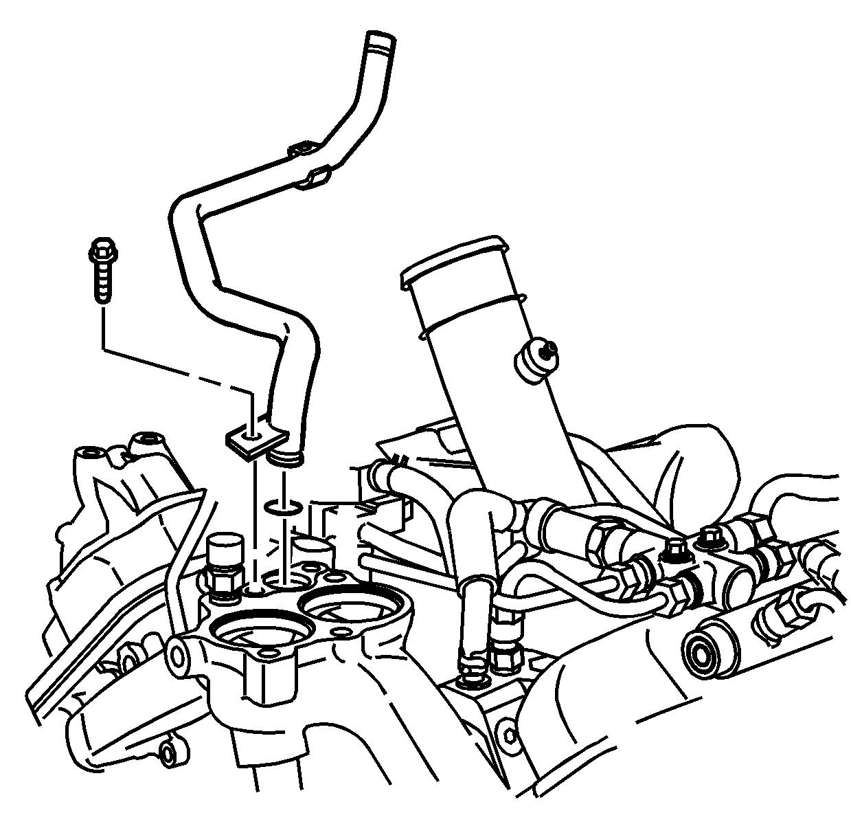
| 11.1. | Install new O-ring lubricated with clean engine oil. |
| 11.2. | Install the heater pipe bracket bolt. |
Tighten
Tighten the bolt to 20 N·m (15 lb ft).
| 11.3. | Install the heater pipe to water crossover bolts. |
Tighten
Tighten the bolts to 20 N·m (15 lb ft).
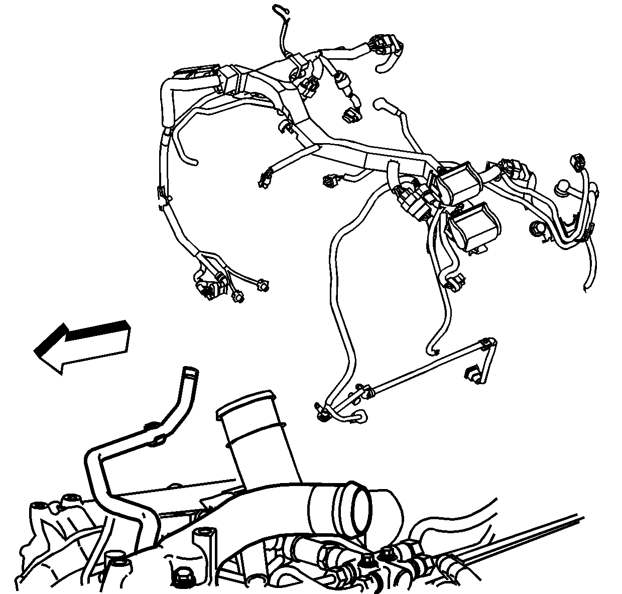
| • | Install upper radiator hose mounting bolts and brackets. |
Tighten
Tighten the bolts to 10 N·m (89 lb ft).
| • | Install the upper radiator hose clamp. |
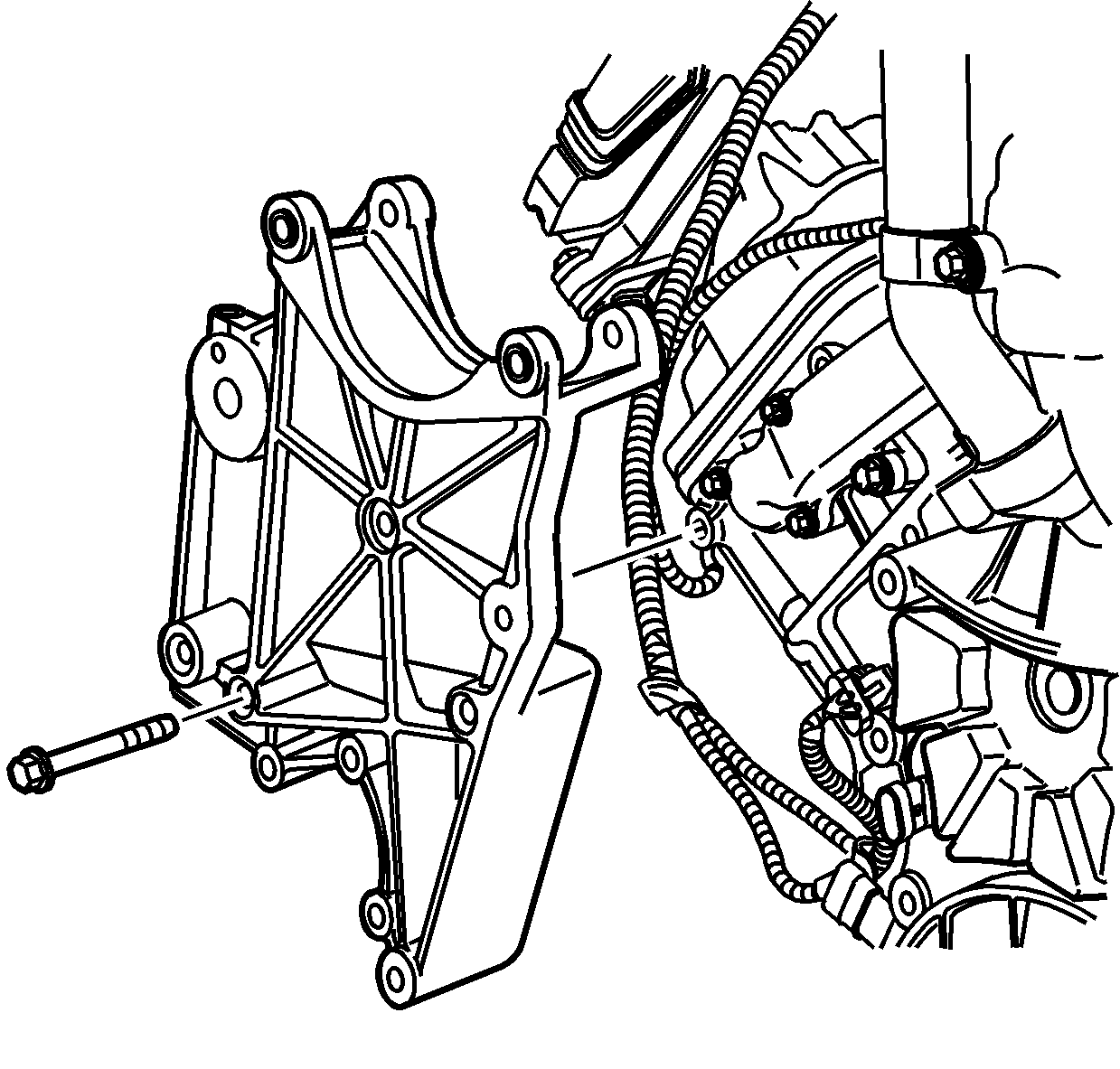
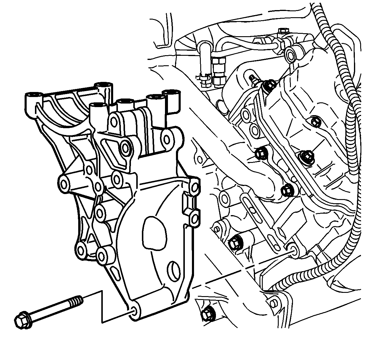
Tighten
Tighten the bolts to 46 N·m (34 lb ft).
