Tools Required
| • | J 7872 Magnetic
Base Dial Indicator |
| • | J 43690 Rod
Bearing Clearance Checking Tool |
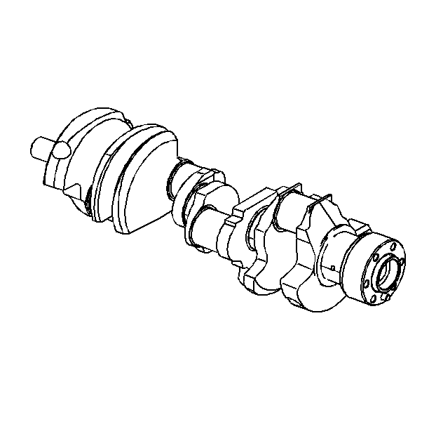
Caution: Wear safety glasses in order to avoid eye damage.
Important: Use care when handling the crankshaft. Avoid damage to the crankshaft
bearing surfaces.
- Clean the crankshaft in cleaning solvent. Remove all sludge or restrictions
from the oil passages.
- Dry the crankshaft with compressed air.
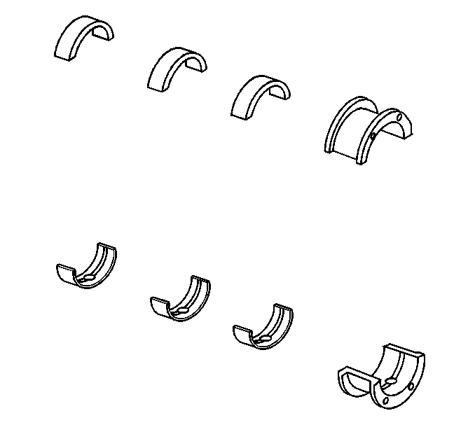
- Clean the crankshaft bearings
in cleaning solvent. Wipe the crankshaft bearings clean with a soft cloth.
Do not scratch the crankshaft bearing surfaces.
- Dry the crankshaft and crankshaft bearings with compressed air.
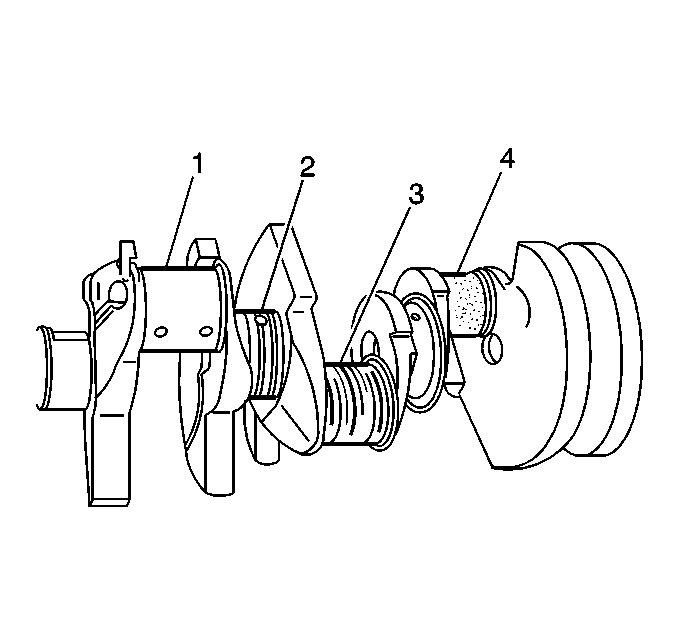
- Inspect the crankshaft
for the following:
| • | Crankshaft journals (1) should be smooth with no evidence
of scoring or damage. |
| • | Scratches or uneven wear (3) |
| • | Wear or damage to the thrust journal surfaces |
| • | Scoring or damage to the rear seal surface |
| • | Restrictions to the oil passages |
| • | Damage to the threaded bolt holes |
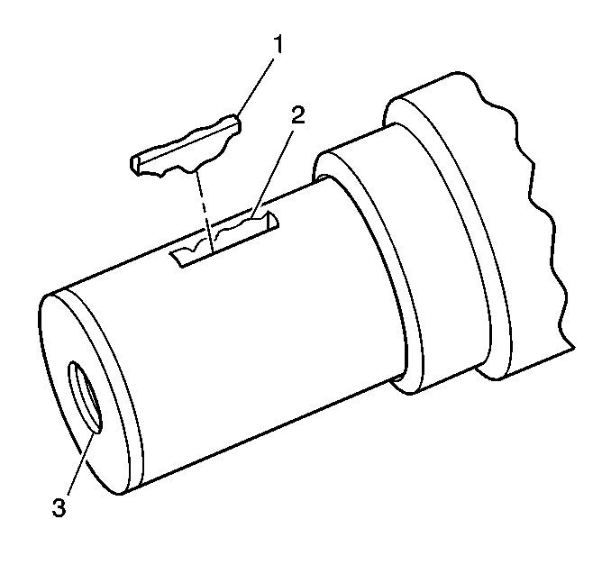
- Inspect the crankshaft
balancer woodruff keys (1), the keyway (2), and the threaded
hole (3) for damage.
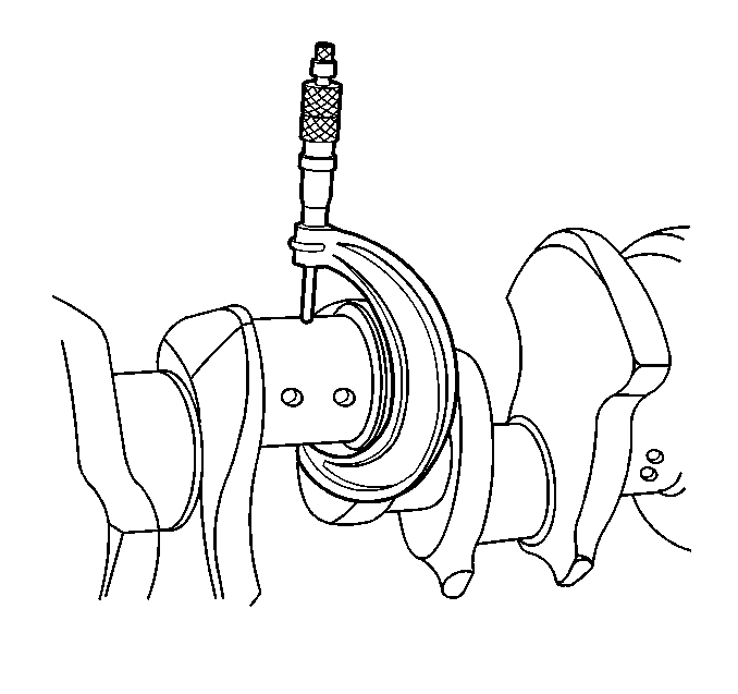
- Measure the crankpins
for out-of-round and taper. Refer to
Engine Mechanical Specifications
.
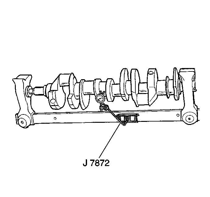
- Using wooden V-blocks,
support the crankshaft on the front and rear journals.
- Use the J 7872
in order to measure crankshaft journal runout.
Refer to
Engine Mechanical Specifications
.
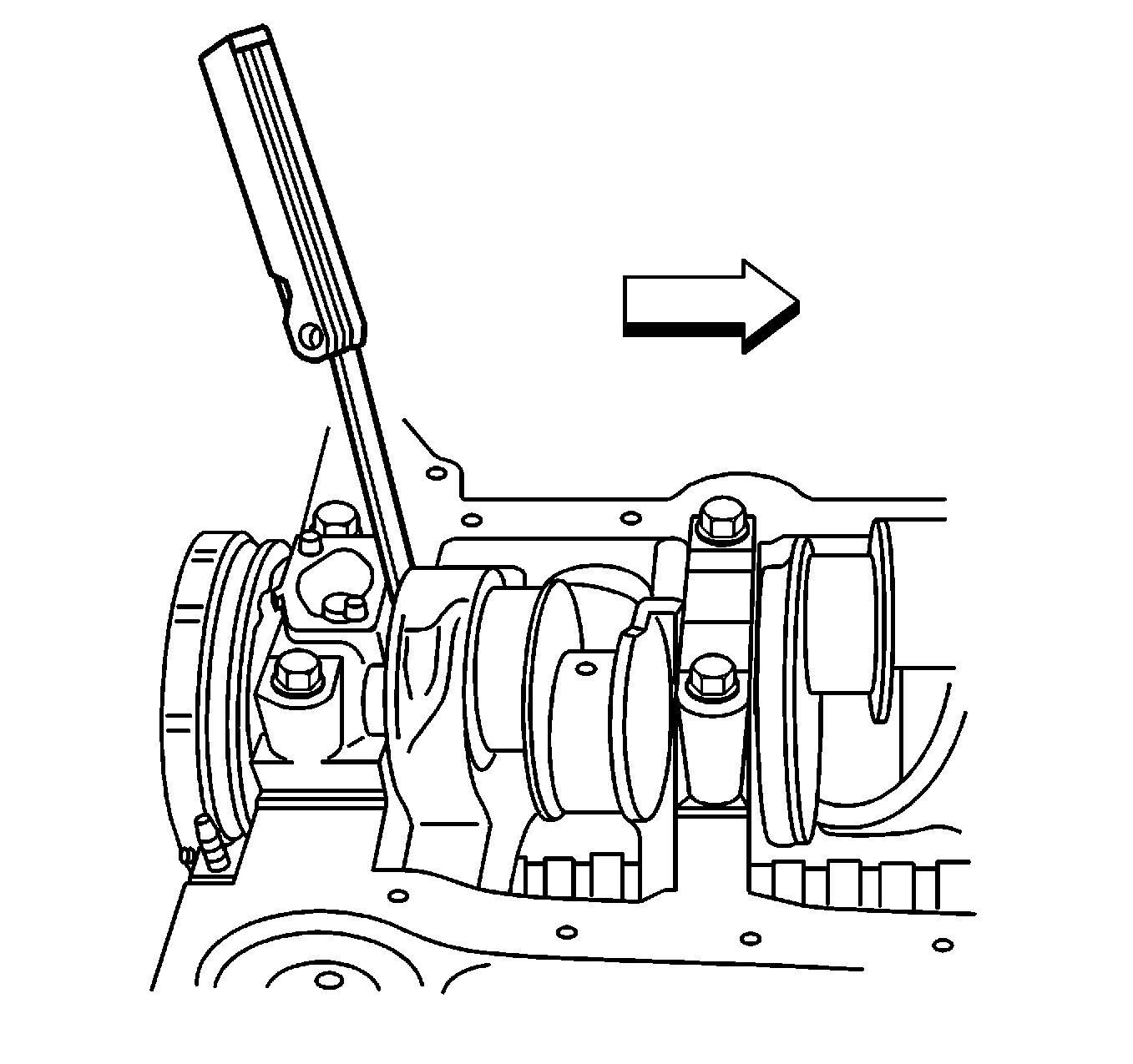
- Measure the crankshaft
end play.
| | Important: In order to properly measure the crankshaft end play, the crankshaft,
the crankshaft bearings, the crankshaft bearing caps, and the fasteners must
be installed into the engine block, and the bolts and studs tightened
finger tight.
|
| 10.1. | Firmly thrust the end of the crankshaft, first rearward then forward.
This will line up the rear crankshaft bearing and the crankshaft thrust surfaces.
Tighten the cap bolts and studs. Refer to
Engine Mechanical Specifications
. |
| 10.2. | With the crankshaft pushed forward, insert a feeler gage between
the crankshaft and the crankshaft bearing surface, then measure the clearance.
Refer to
Engine Mechanical Specifications
. |
| 10.3. | Turn the crankshaft to check for binding. If the crankshaft does
not turn freely, loosen the crankshaft bearing bolts and studs, one crankshaft
bearing cap at a time, until the tight crankshaft bearing is located. |
Burrs on the crankshaft bearing cap or engine block, foreign matter
between the crankshaft bearing and the crankshaft bearing cap or the engine
block, or a faulty crankshaft bearing could cause a lack of clearance
between the crankshaft and crankshaft bearing.
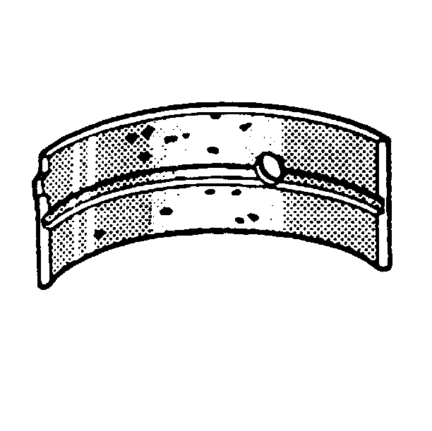
- Inspect the crankshaft
bearings for craters or pockets. Flattened sections on the crankshaft bearing
halves also indicate fatigue.
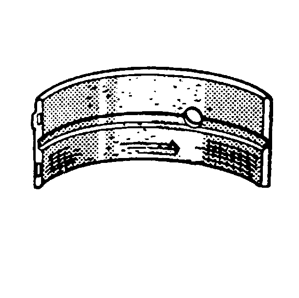
- Inspect the crankshaft
bearings for excessive scoring or discoloration.
- Inspect the crankshaft bearings for dirt or debris imbedded into
the crankshaft bearing material.
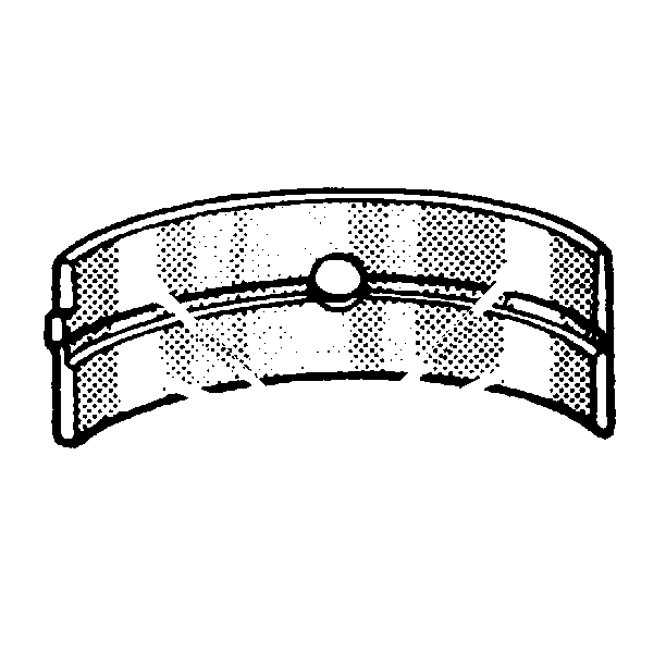
- Inspect the crankshaft
bearings for improper seating indicated by bright, polished sections of the
crankshaft bearings.
| • | If the lower half of the crankshaft bearing is worn or damaged,
both the upper and lower halves of the crankshaft bearing should be replaced. |
| • | Generally, if the lower half of the crankshaft bearing is suitable
for use, the upper half of the crankshaft bearing should also be suitable
for use. |
Measuring Crankshaft Bearing Clearances
| • |

Notice: Do not shim, scrape, or file bearing inserts. Do not touch the bearing
surface of the insert with bare fingers. Skin oil and acids will etch the
bearing surface.
The crankshaft bearings are precision insert type and do not use shims
for adjustment. If the clearances are excessive, then new upper and lower
crankshaft bearings will be required. The service crankshaft bearings
are available in the standard size and an undersize. |
| • | The selective fitting of the crankshaft bearings are necessary
in production in order to obtain close tolerances. For this reason, in one
journal bore you may use one-half of a standard crankshaft bearing with
one-half of an undersize crankshaft bearing. |
| • | In order to determine the correct replacement bearing size, the
bearing clearance must be measured accurately. When checking main bearing
clearances, either the micrometer or plastic gage method may be used.
The micrometer method gives more reliable results and is preferred. When
checking connecting rod bearing clearances, the plastic gage method will
result in unreliable measurements. The use of J 43690
is preferred. |
| • | If the crankshaft bearing clearance is within specifications,
the crankshaft bearing is satisfactory. If the clearance is not within specifications,
replace the crankshaft bearing. Always replace both the upper and lower
crankshaft bearings as a unit. |
| • | A standard, or undersize crankshaft bearing combination, may result
in the proper clearance. If the proper crankshaft bearing clearance cannot
be achieved using the standard or the undersize crankshaft bearings, it
may be necessary to repair or replace the crankshaft. |
Measuring Crankshaft Bearing Clearances - Micrometer Method

- Measure the crankshaft
journal diameter with a micrometer in several places, approximately 90 degrees
apart. Average the measurements.
- Determine the taper and out-of-round of the journal. Refer to
Engine Mechanical Specifications
.
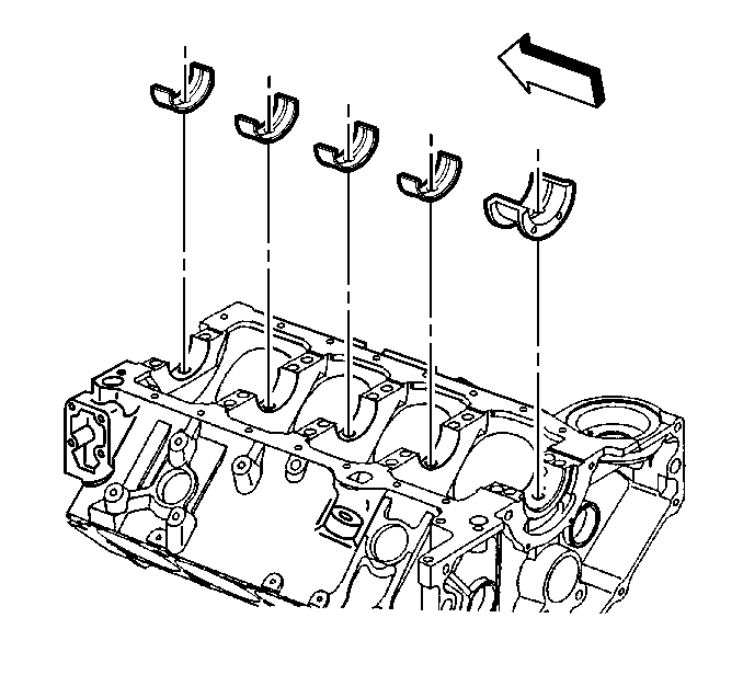
- Install the bearings into the engine block.
Notice: Use the correct fastener in the correct location. Replacement fasteners
must be the correct part number for that application. Fasteners requiring
replacement or fasteners requiring the use of thread locking compound or sealant
are identified in the service procedure. Do not use paints, lubricants, or
corrosion inhibitors on fasteners or fastener joint surfaces unless specified.
These coatings affect fastener torque and joint clamping force and may damage
the fastener. Use the correct tightening sequence and specifications when
installing fasteners in order to avoid damage to parts and systems.
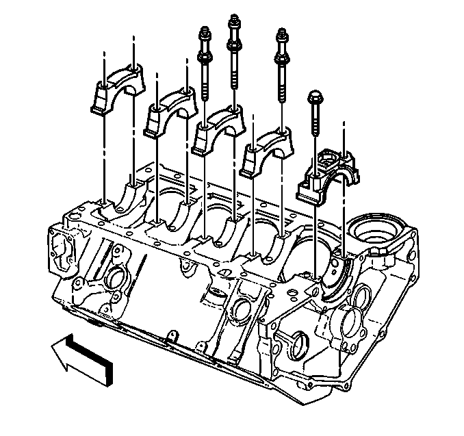
- Install the bearing
cap bolts and tighten to specifications. Refer to
Fastener Tightening Specifications
.
- Measure the bearing inside diameter (ID) at the top and
bottom.
- In order to determine the bearing clearance, subtract the average
journal diameter from the bearing inside diameter.
- Compare the readings to specifications. Refer to
Engine Mechanical Specifications
.
- Replace bearing halves as required to obtain the proper bearing
clearances.
Measuring Connecting Rod Bearing Clearances - J 43690
Method
- Remove the oil pan and other necessary components to gain access to
the connecting rods. Remove the oil pump, screen, and deflector, when applicable.
- Rotate the crankshaft until the crankshaft journal/connecting
rod to be measured is in the 10 o'clock position.
Important: The crankshaft must be secure, with no movement or rotation, in order
to obtain an accurate reading. Remove an intermediate bearing cap, as required,
in order to secure the crankshaft and allow measurement of connecting
rod bearing clearances.
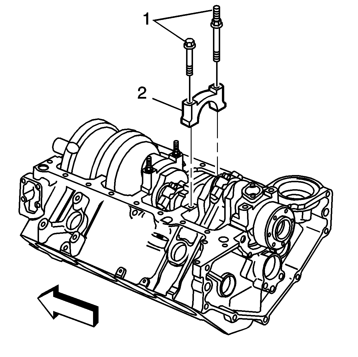
- Remove the bearing cap bolts (1), cap (2) and bearing
half.
- Insert a piece of paper card stock onto the crankshaft journal.
Install the bearing half, bearing cap, and bolts. Refer to
Fastener Tightening Specifications
.
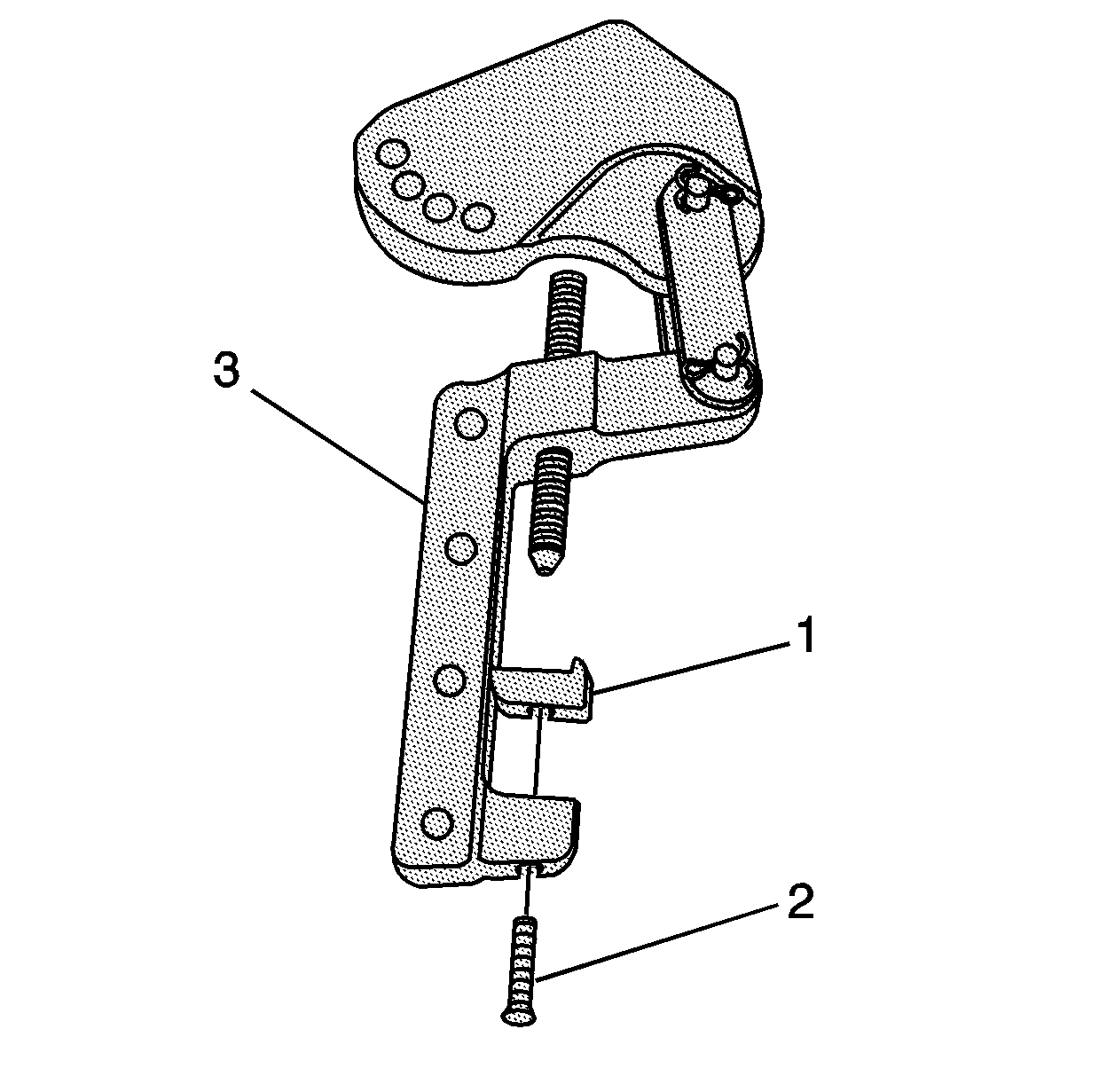
- Install the foot (1) and bolt (2) to the pivot arm assembly (3).
- Tighten the bolt until snug.
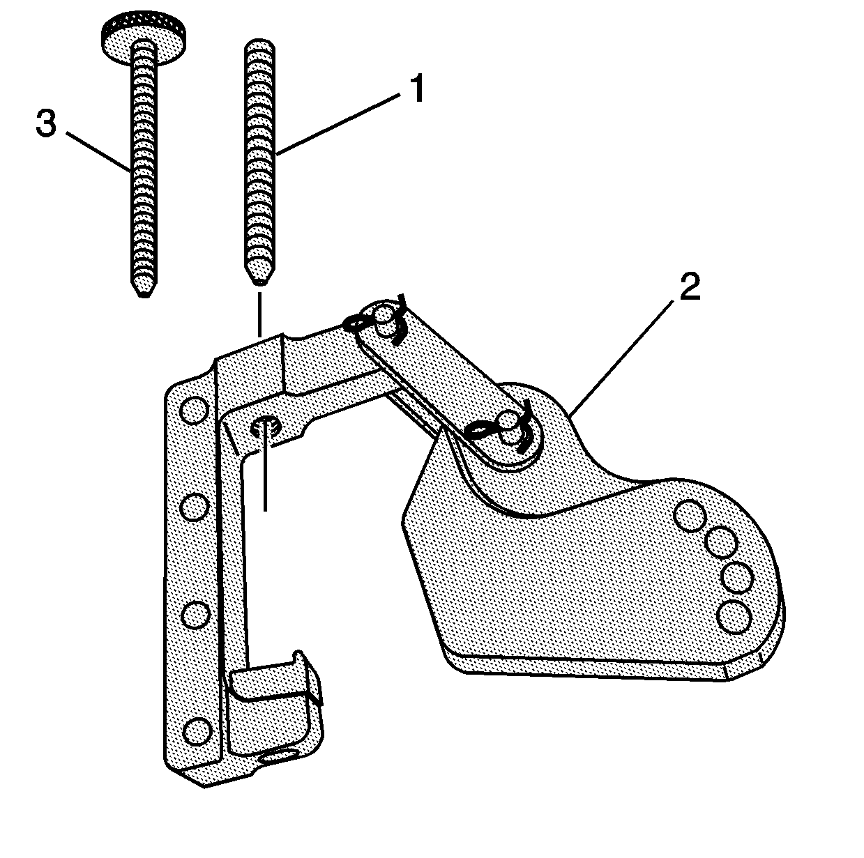
- Install the screw (1 or 3) to the pivot arm assembly (2).
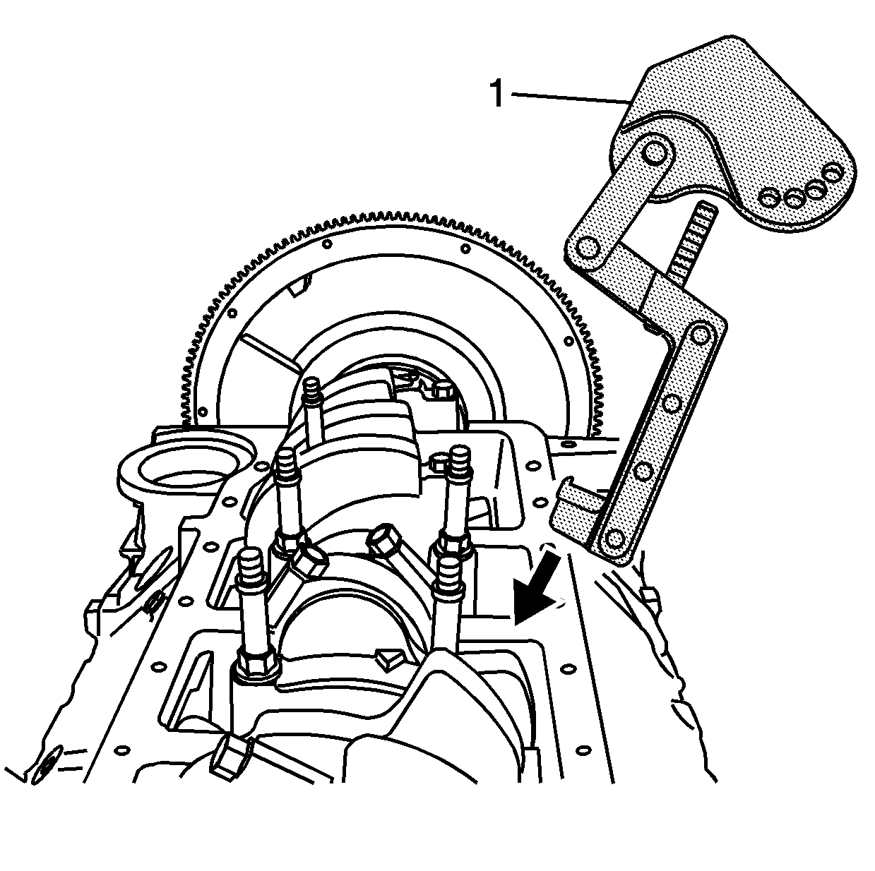
- Install the pivot arm assembly (1) onto the connecting rod.
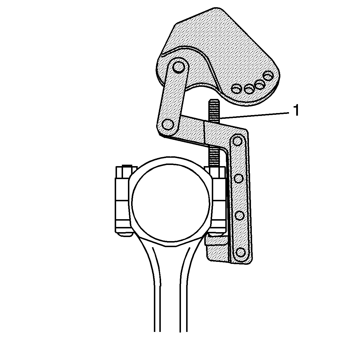
- Position the foot of the pivot arm assembly over the large end of the
connecting rod bolt.
- Position the screw (1) onto the small end of the connecting
rod bolt and tighten securely.
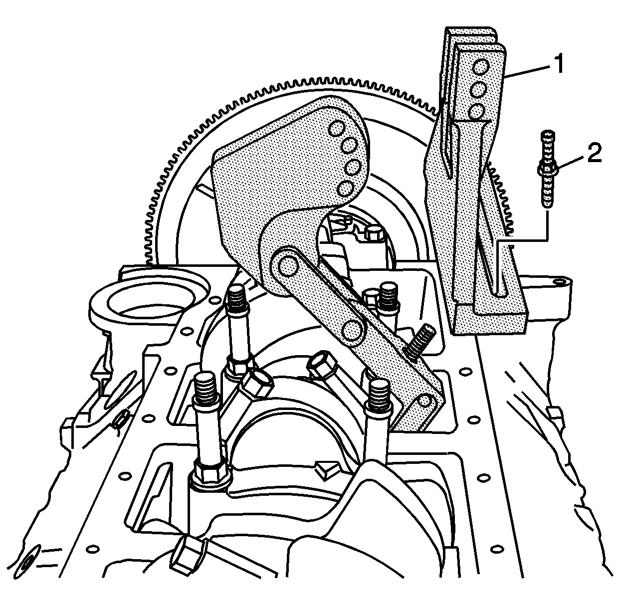
- Install the base (1)
and bolt (2) to the oil pan rail.
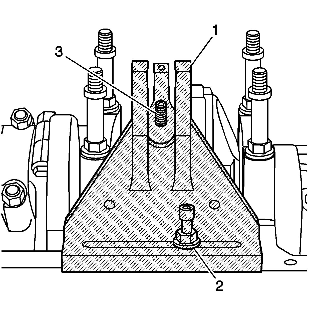
- Align the center of the base (1) with the screw (3) of
the pivot arm assembly.
- Tighten the bolt (2) until snug.
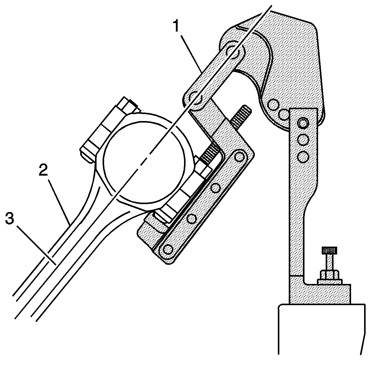
- Align the link (1)
of the pivot arm assembly on a plane (3) equal to that of the connecting
rod beam (2).
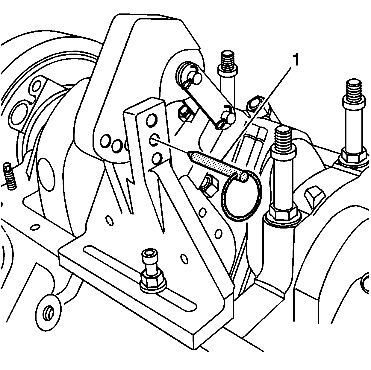
- With the link of the pivot arm assembly aligned to the beam of the connecting
rod, position the pivot arm to the base and insert the pin (1).
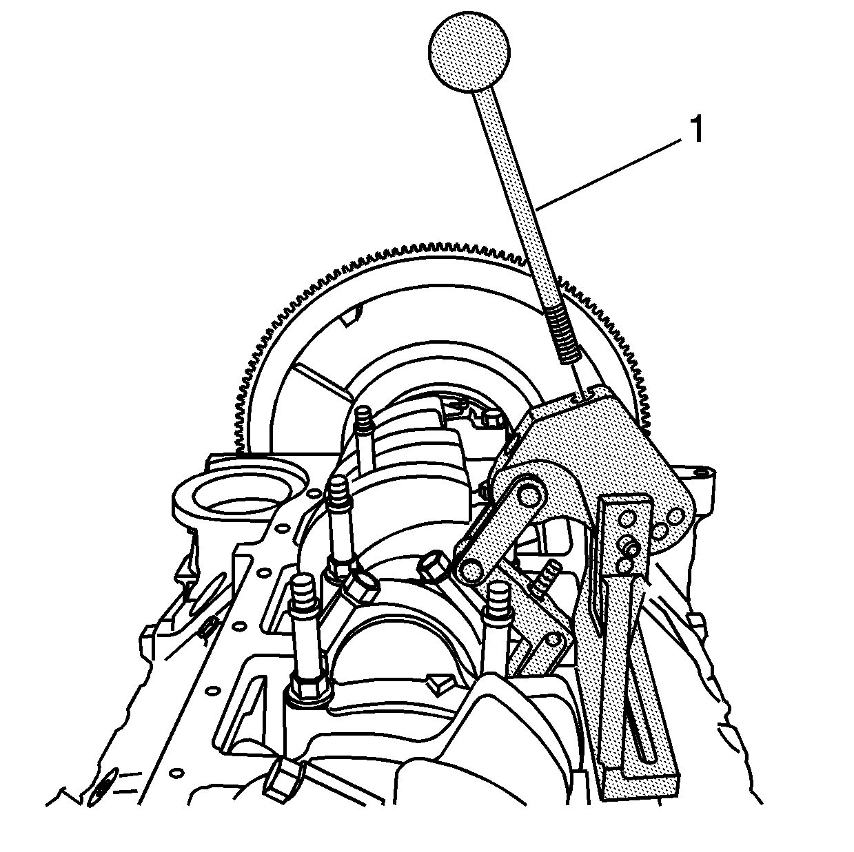
- Insert the handle (1)
to the pivot arm assembly.
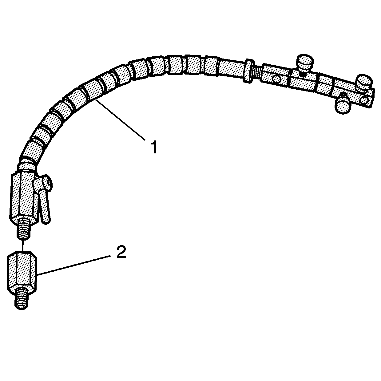
- Select the adapter (2), as required, and install to the swivel
base (1).
- Tighten until snug.
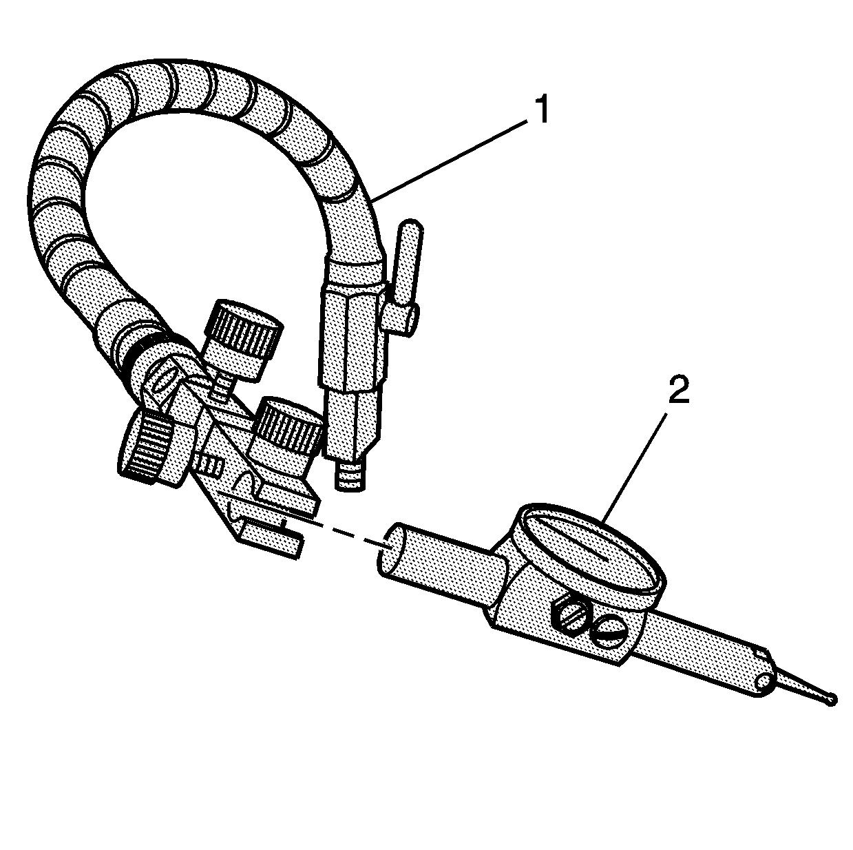
Important: The clamp of the swivel base and the shaft of the indicator should be
free of oil or other debris. A loose or improperly clamped indicator may indicate
incorrect readings.
- Install the indicator (2) to the swivel base (1).
- Tighten the clamp of the base until snug.
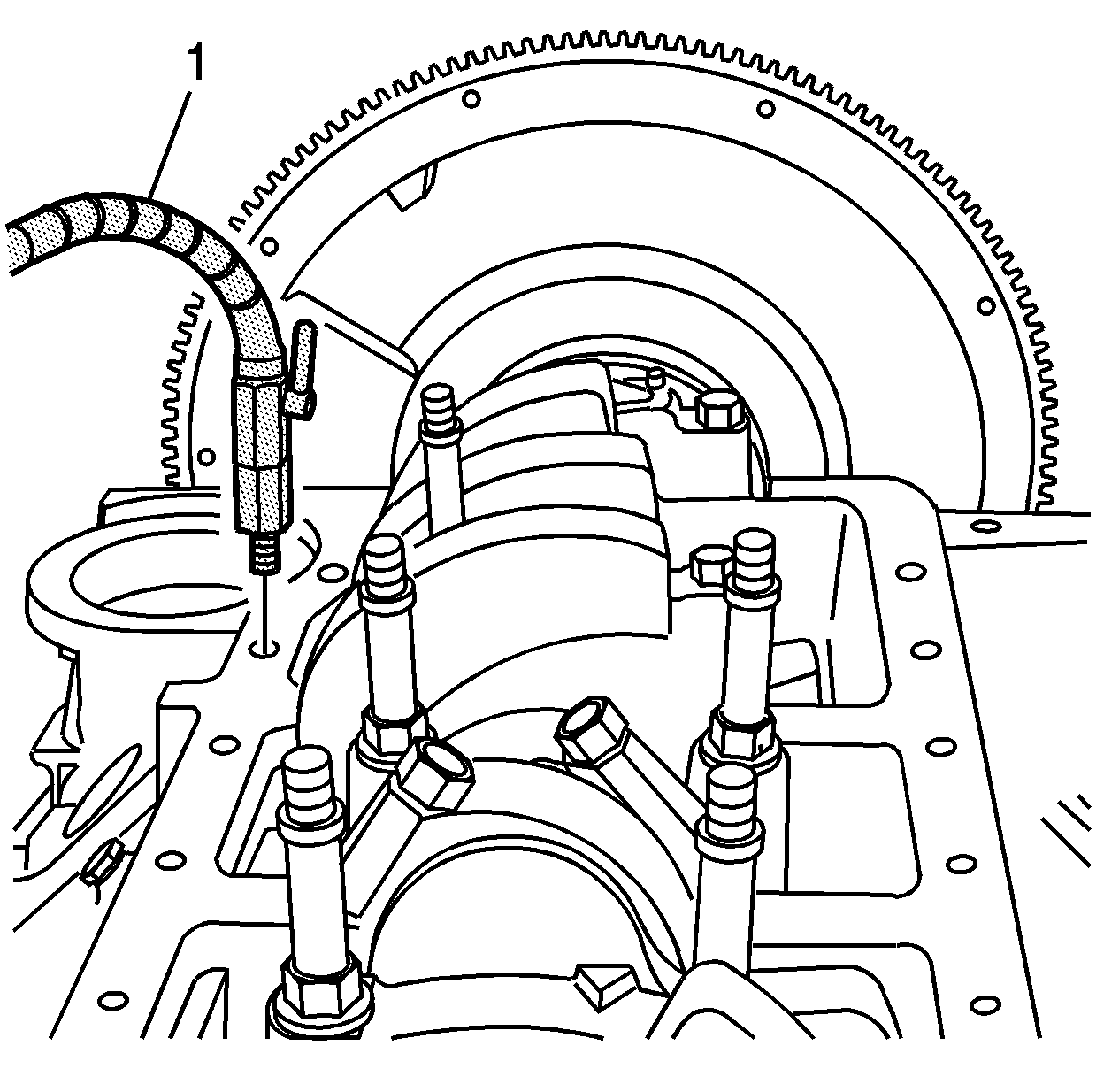
- Install the swivel base (1) to the oil pan rail of the engine
block.
- Tighten until snug.
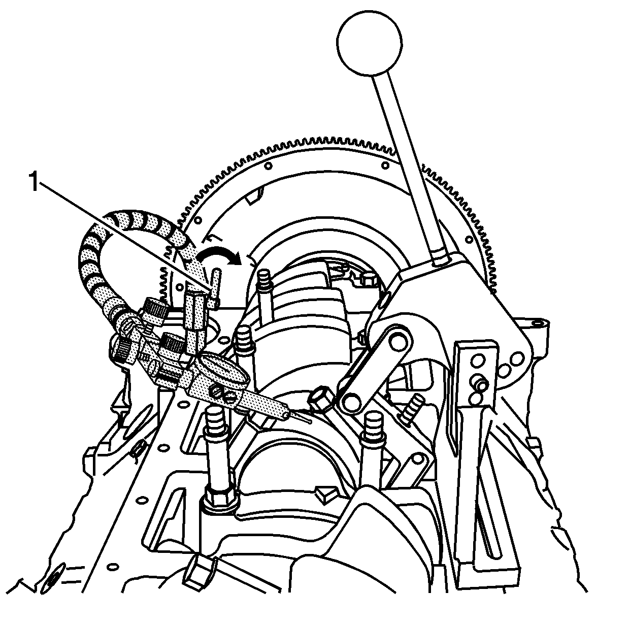
- Adjust the swivel base
as required, and position the indicator tip slightly above the connecting
rod cap. Lock the swivel base in position by rotating the locking lever (1).
Do not allow the tip of the indicator to contact the connecting rod at
this time.
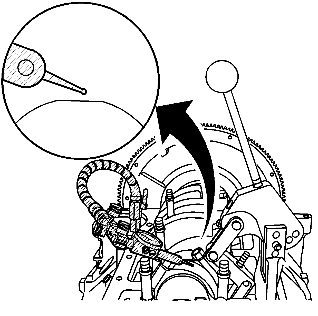
- The tip of the indicator should be positioned above, and NOT in contact
with the cap end of the connecting rod.
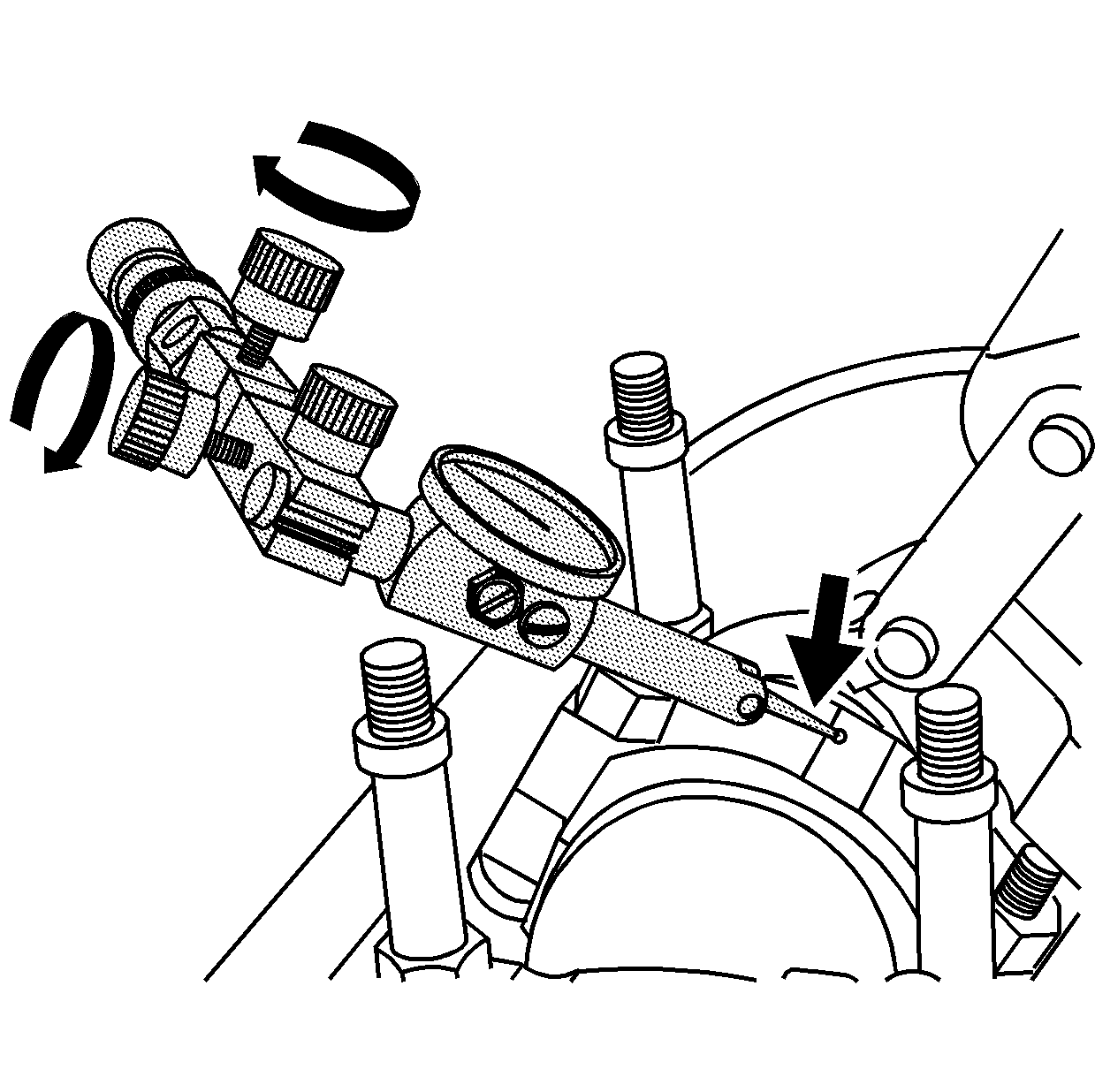
- Rotate the fine adjustment knobs, on the dial indicator end of the swivel
base, to position the tip of the indicator in contact with the connecting
rod.
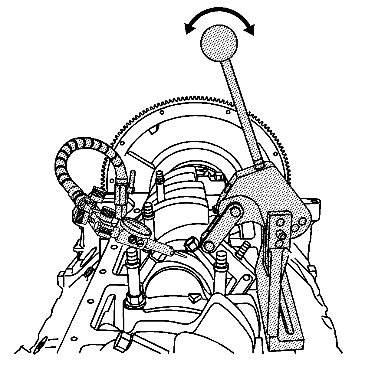
- Lightly actuate the handle
of the pivot arm assembly, multiple times in both directions, to ensure the
oil film is removed from the journal.
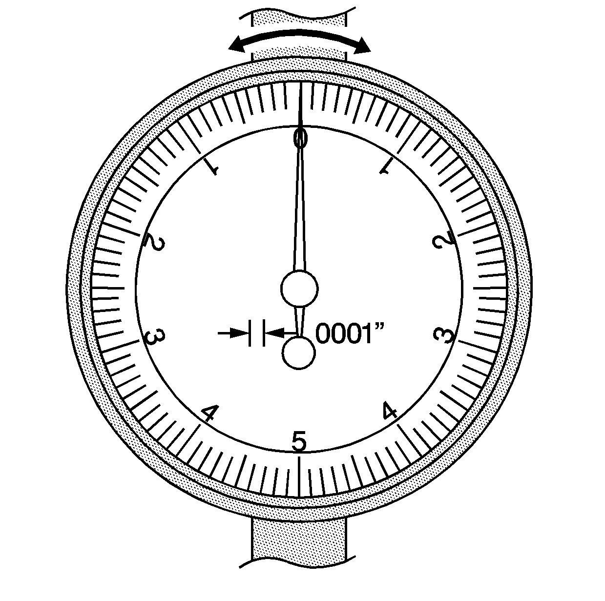
- Load the handle in the
forward position and zero the dial indicator. Load the handle multiple times
in both directions and record the reading.
Important: During this procedure, card stock may enter the crankshaft journal oil
galleries. Remove all card stock from the bearing journal and oil galleries
prior to reassembly.
- Remove the bearing cap bolts, cap, and paper stock.
- Replace bearing halves, as required, to obtain the proper bearing
clearances.
- Install the bearings, cap, and bolts. Refer to
Fastener Tightening Specifications
.
Measuring Crankshaft Bearing Clearances - Plastic Gage Method

- Install the crankshaft bearings into the engine block.
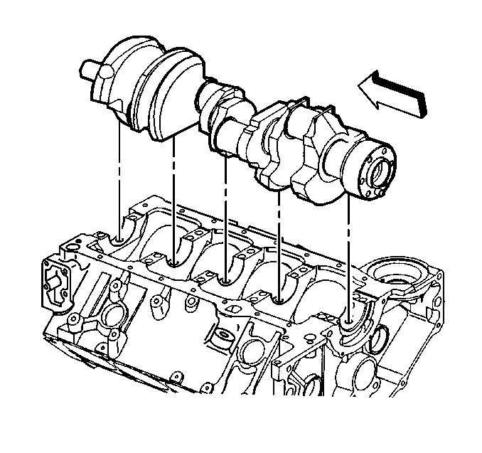
- Install the crankshaft.
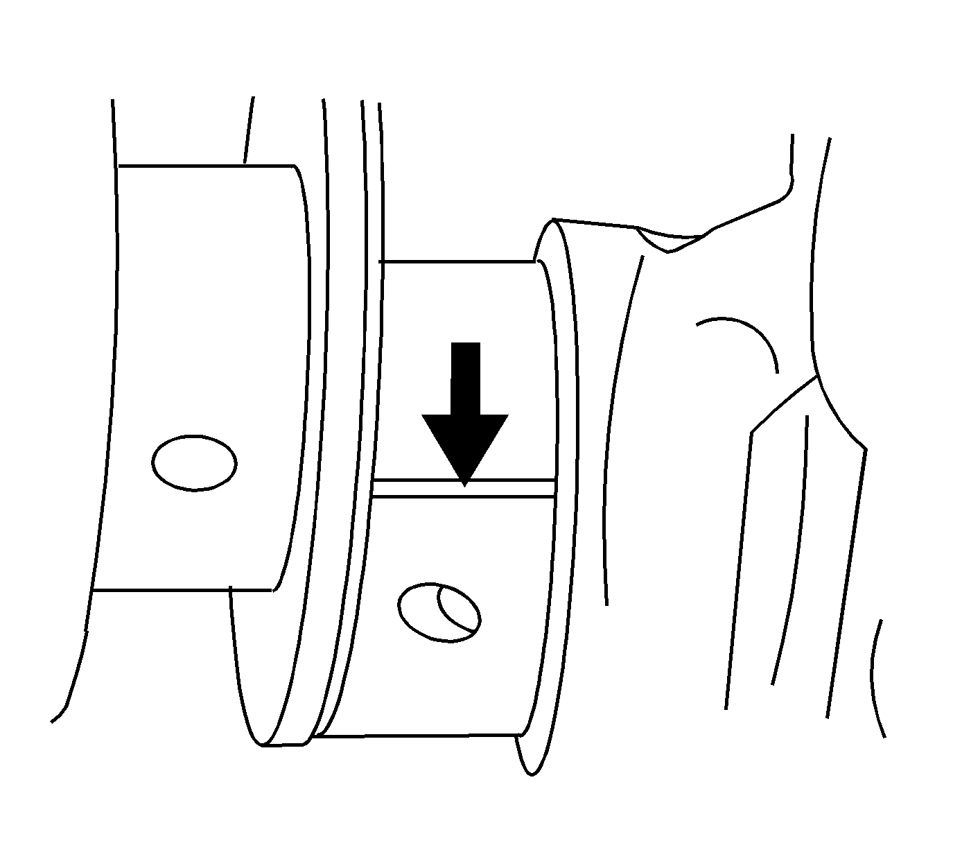
- Install the gaging plastic
the full width of the journal.
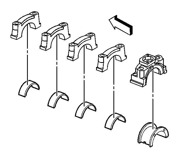
- Install the crankshaft bearings into the crankshaft bearing caps.
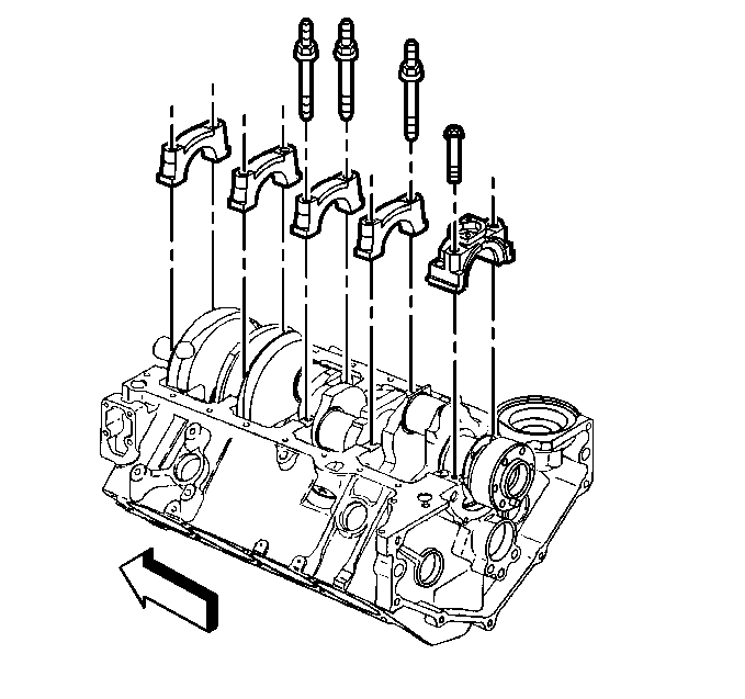
- Install the crankshaft
bearing caps in the original positions, and the arrow on the crankshaft bearing
caps in the direction of the front of the engine block.
Notice: Use the correct fastener in the correct location. Replacement fasteners
must be the correct part number for that application. Fasteners requiring
replacement or fasteners requiring the use of thread locking compound or sealant
are identified in the service procedure. Do not use paints, lubricants, or
corrosion inhibitors on fasteners or fastener joint surfaces unless specified.
These coatings affect fastener torque and joint clamping force and may damage
the fastener. Use the correct tightening sequence and specifications when
installing fasteners in order to avoid damage to parts and systems.
- Install the crankshaft
bearing cap bolts and the crankshaft bearing cap studs. Refer to
Fastener Tightening Specifications
.
- Remove the crankshaft bearing cap bolts and studs.
- Remove the crankshaft bearing caps. The gaging plastic may adhere
to either the crankshaft bearing journal or the crankshaft bearing surface.
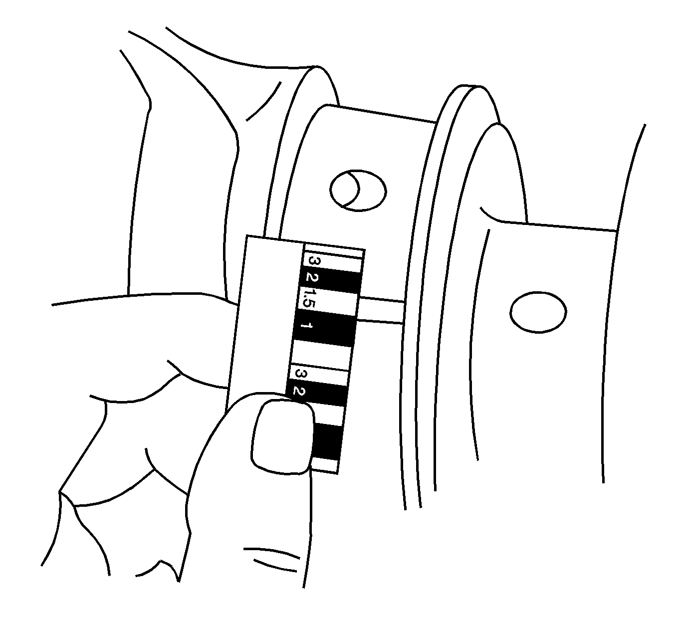
- Without removing the gaging
plastic, measure the compressed width at the widest point, using the graduated
scale on the edge of the gaging plastic envelope.
If the flattened gaging plastic tapers toward the middle or the ends,
there may be a difference in clearance indicating taper, low spot or other
irregularity of the crankshaft bearing or the crankshaft bearing journal.
- Remove the flattened gaging plastic.
- Measure the remaining crankshaft bearing journals.
Measuring Connecting Rod Bearing Side Clearance
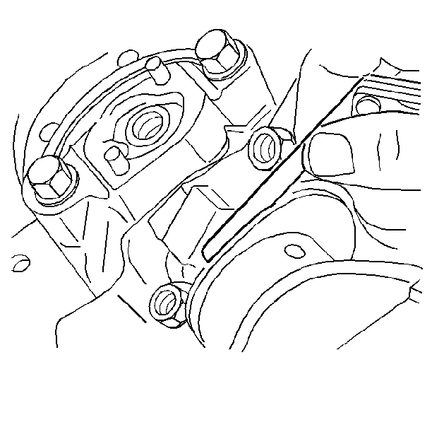
- Insert a feeler gage between
the connecting rod caps and measure the connecting rod side clearance.
Refer to
Engine Mechanical Specifications
.
- The connecting rod side clearances may also be measured with a
dial indicator set.
Tools Required
| • | J 7872
Magnetic
Base Dial Indicator |
| • | J 43690
Rod
Bearing Clearance Checking Tool |

Caution: Wear safety glasses in order to avoid eye damage.
Important: Use care when handling the crankshaft. Avoid damage to the crankshaft
bearing surfaces.
- Clean the crankshaft in cleaning solvent. Remove all sludge or restrictions
from the oil passages.
- Dry the crankshaft with compressed air.

- Clean the crankshaft bearings
in cleaning solvent. Wipe the crankshaft bearings clean with a soft cloth,
do not scratch the crankshaft bearing surfaces.
- Dry the crankshaft and crankshaft bearings with compressed air.

- Inspect the crankshaft
for the following:
| • | Crankshaft journals (1) should be smooth with no evidence
of scoring or damage. |
| • | Scratches or uneven wear (3) |
| • | Wear or damage to the thrust journal surfaces |
| • | Scoring or damage to the rear seal surface |
| • | Restrictions to the oil passages |
| • | Damage to the threaded bolt holes |

- Inspect the woodruff keys
(crankshaft balancer) (1), the keyway (2), and the threaded
hole (3) for damage.

- Measure the crankpins
for out-of-round and taper. Refer to
Engine Mechanical Specifications
.

- Using wooden V-blocks,
support the crankshaft on the front and rear journals.
- Use the
J 7872
in order to measure crankshaft journal runout.
Refer to
Engine Mechanical Specifications
.

- Measure the crankshaft
end play.
| | Important: In order to properly measure the crankshaft end play, the crankshaft,
the crankshaft bearings, the crankshaft bearing caps, and the fasteners must
be installed into the engine block and the bolts and studs tightened. Refer
to
Engine Mechanical Specifications
.
|
| 10.1. | Firmly thrust the end of the crankshaft first rearward then forward.
This will line up the rear crankshaft bearing and the crankshaft thrust surfaces. |
| 10.2. | With the crankshaft pushed forward, insert a feeler gage between
the crankshaft and the crankshaft bearing surface and then measure the clearance.
Refer to
Engine Mechanical Specifications
. |
| 10.3. | Turn the crankshaft to check for binding. If the crankshaft does
not turn freely, loosen the crankshaft bearing bolts and studs, one crankshaft
bearing cap at a time, until the tight crankshaft bearing is located. |
Burrs on the crankshaft bearing cap or engine block, foreign matter
between the crankshaft bearing and the crankshaft bearing cap or the engine
block, or a faulty crankshaft bearing could cause a lack of clearance between
the crankshaft and crankshaft bearing.

- Inspect the crankshaft
bearings for craters or pockets. Flattened sections on the crankshaft bearing
halves also indicate fatigue.

- Inspect the crankshaft
bearings for excessive scoring or discoloration.
- Inspect the crankshaft bearings for dirt or debris imbedded into
the crankshaft bearing material.

- Inspect the crankshaft
bearings for improper seating indicated by bright, polished sections of the
crankshaft bearings.
| • | If the lower half of the crankshaft bearing is worn or damaged,
both the upper and lower halves of the crankshaft bearing should be replaced. |
| • | Generally, if the lower half of the crankshaft bearing is suitable
for use, the upper half of the crankshaft bearing should also be suitable
for use. |
Measuring Crankshaft Bearing Clearances
| • |

Notice: Do not shim, scrape, or file bearing inserts. Do not touch the bearing
surface of the insert with bare fingers. Skin oil and acids will etch the
bearing surface.
The crankshaft bearings are of the precision insert type and do not
use shims for adjustment. If the clearances are excessive, then new upper
and lower crankshaft bearings will be required. The service crankshaft bearings
are available in the standard size and an undersize. |
| • | The selective fitting of the crankshaft bearings are necessary
in production in order to obtain close tolerances. For this reason, in one
journal bore you may use one-half of a standard crankshaft bearing with one-half
of an undersize crankshaft bearing. |
| • | In order to determine the correct replacement bearing size, the
bearing clearance must be measured accurately. When checking main bearing
clearances, either the micrometer or plastic gage method may be used; however,
the micrometer method gives more reliable results and is preferred. When checking
connecting rod bearing clearances, the plastic gage method will result in
unreliable measurements. The use of
J 43690
is preferred. |
| • | Normally the crankshaft bearing journals wear evenly and are not
out-of-round. However, if a crankshaft bearing is being fitted to an out-of-round
0.0254 mm (0.0010 in) (maximum) crankshaft bearing journal,
be sure to fit to the maximum diameter of the crankshaft bearing journal.
If the crankshaft bearing is fitted to the minimum diameter and the crankshaft
bearing journal is excessively out-of-round, the interference between the
crankshaft bearing and the crankshaft bearing journal will result in rapid
crankshaft bearing failure. |
| • | If the crankshaft bearing clearance is within specifications,
the crankshaft bearing is satisfactory. If the clearance is not within specifications,
replace the crankshaft bearing. Always replace both the upper and lower crankshaft
bearings as a unit. |
| • | A standard or undersize crankshaft bearing combination may result
in the proper clearance. If the proper crankshaft bearing clearance cannot
be achieved using the standard or the undersize crankshaft bearings, it may
be necessary to repair or replace the crankshaft. |
Measuring Crankshaft Bearing Clearances (Micrometer Method)

- Measure the crankshaft
journal diameter with a micrometer in several places, approximately 90 degrees
apart. Average the measurements.
- Determine the taper and out-of-round of the journal. Refer to
Engine Mechanical Specifications
.

- Install the bearings into the engine block or connecting rod assembly.

- Install the bearing cap
bolts and tighten to specifications. Refer to
Fastener Tightening Specifications
.
- Measure the bearing inside diameter (ID) at two points 90 degrees
apart. Average the measurements.
- In order to determine the bearing clearance, subtract the average
journal diameter from the average bearing inside diameter.
- Compare the readings to specifications. Refer to
Engine Mechanical Specifications
.
- Replace bearing halves as required to obtain the proper bearing
clearances.
Measuring Connecting Rod Bearing Clearances (J 43690 Method)
- Remove the oil pan and other necessary components to gain access
to the connecting rods. Remove the oil pump, screen, and deflector (when applicable).
- Rotate the crankshaft until the crankshaft journal/connecting
rod to be measured is in the 10 O'clock position.

Important: The crankshaft must be secure with no movement or rotation in order
to obtain an accurate reading. Remove an intermediate bearing cap (as required)
in order to secure the crankshaft and allow measurement of connecting rod
bearing clearances.
- Remove the bearing cap bolts (1), cap (2) and bearing
half.
Notice: Use the correct fastener in the correct location. Replacement fasteners
must be the correct part number for that application. Fasteners requiring
replacement or fasteners requiring the use of thread locking compound or sealant
are identified in the service procedure. Do not use paints, lubricants, or
corrosion inhibitors on fasteners or fastener joint surfaces unless specified.
These coatings affect fastener torque and joint clamping force and may damage
the fastener. Use the correct tightening sequence and specifications when
installing fasteners in order to avoid damage to parts and systems.
- Insert a piece of
paper card stock onto the crankshaft journal. Install the bearing half, bearing
cap, and bolts. Refer to
Fastener Tightening Specifications
.

- Install the foot (1) and bolt (2) to the pivot arm assembly (3).
Tighten the bolt until snug.

- Install the screw (1 or 3) to the pivot arm assembly (2).

- Install the pivot arm assembly (1) onto the connecting rod.

- Position the foot of the pivot arm assembly over the large end of the
connecting rod bolt.
- Position the screw (1) onto the small end of the connecting
rod bolt and tighten securely.

- Install the base (1)
and bolt (2) to the oil pan rail.

- Align the center of the base (1) with the screw (3) of
the pivot arm assembly. Tighten the bolt (2) until snug.

- Align the link (1)
of the pivot arm assembly on a plane (3) equal to that of the connecting
rod beam (2).

- With the link of the pivot arm assembly aligned to the beam of the connecting
rod, position the pivot arm to the base and insert the pin (1).

- Insert the handle (1)
to the pivot arm assembly.

- Select the adapter (2) (as required) and install to the swivel
base (1). Tighten until snug.

Important: The clamp of the swivel base and the shaft of the indicator should be
free of oil or other debris. A loose or improperly clamped indicator may indicate
incorrect readings.
- Install the indicator (2) to the swivel base (1). Tighten
the clamp of the base until snug.

- Install the swivel base (1) to the oil pan rail of the engine
block. Tighten until snug.

- Adjust the swivel base
as required and position the indicator tip slightly above the connecting rod
cap. Lock the swivel base in position by rotating the locking lever (1).
Do not allow the tip of the indicator to contact the connecting rod at this
time.

- The tip of the indicator should be positioned above and NOT in contact
with the cap end of the connecting rod.

- Rotate the fine adjustment knobs on the dial indicator end of the swivel
base to position the tip of the indicator in contact with the connecting rod.

- Lightly actuate the handle
of the pivot arm assembly (multiple times in both directions) to ensure the
oil film is removed from the journal.

- Load the handle in the
forward position and zero the dial indicator. Load the handle multiple times
in both directions and record the reading.
Important: During this procedure, card stock may enter the crankshaft journal oil
galleries. Be sure to remove all card stock from the bearing journal and oil
galleries prior to reassembly.
- Remove the bearing cap bolts, cap, and paper stock.
- Replace bearing halves as required to obtain the proper bearing
clearances.
- Install the bearings, cap, and bolts. Refer to
Fastener Tightening Specifications
.
Measuring Crankshaft Bearing Clearances (Plastic Gage Method)

- Install the crankshaft bearings into the engine block.

- Install the crankshaft.

- Install the gaging plastic
the full width of the journal.

- Install the crankshaft bearings into the crankshaft bearing caps.

- Install the crankshaft
bearing caps in the original positions and the arrow on the crankshaft bearing
caps in the direction of the front of the engine block.
Notice: Use the correct fastener in the correct location. Replacement fasteners
must be the correct part number for that application. Fasteners requiring
replacement or fasteners requiring the use of thread locking compound or sealant
are identified in the service procedure. Do not use paints, lubricants, or
corrosion inhibitors on fasteners or fastener joint surfaces unless specified.
These coatings affect fastener torque and joint clamping force and may damage
the fastener. Use the correct tightening sequence and specifications when
installing fasteners in order to avoid damage to parts and systems.
- Install the crankshaft
bearing cap bolts and the crankshaft bearing cap studs. Refer to
Fastener Tightening Specifications
.
- Remove the crankshaft bearing cap bolts and studs.
- Remove the crankshaft bearing caps. The gaging plastic may adhere
to either the crankshaft bearing journal or the crankshaft bearing surface.

- Without removing the gaging
plastic, measure the compressed width at the widest point using the graduated
scale on the edge of the gaging plastic envelope.
If the flattened gaging plastic tapers toward the middle or the ends,
there may be a difference in clearance indicating taper, low spot or other
irregularity of the crankshaft bearing or the crankshaft bearing journal.
- Remove the flattened gaging plastic.
- Measure the remaining crankshaft bearing journals.
Measuring Connecting Rod Bearing Side Clearance

- Insert a feeler gage between
the connecting rod caps and measure the connecting rod side clearance. Refer
to
Engine Mechanical Specifications
.
- The connecting rod side clearances may also be measured with a
dial indicator set.


