Removal Procedure
- Disconnect the negative battery cable.
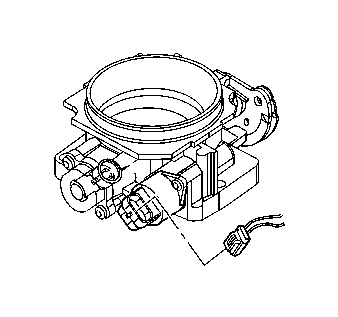
- Disconnect the IAC harness connector.
- Remove the IAC valve attaching fasteners.
- Remove the IAC valve assembly.
- Remove the O-ring.
Caution: Unless directed otherwise, the ignition and start switch must be in the OFF or LOCK position, and all electrical loads must be OFF before servicing any electrical component. Disconnect the negative battery cable to prevent an electrical spark should a tool or equipment come in contact with an exposed electrical terminal. Failure to follow these precautions may result in personal injury and/or damage to the vehicle or its components.
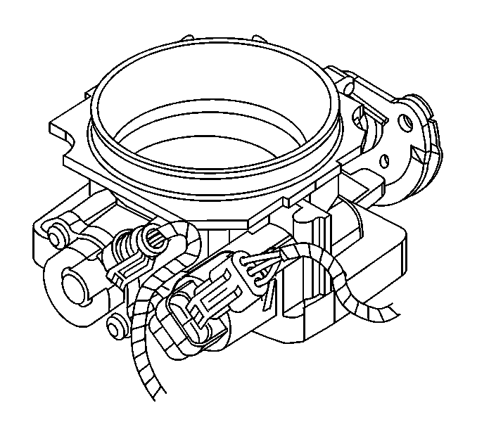
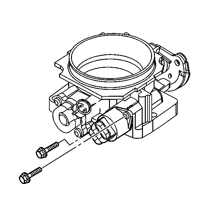
Notice: If the IAC valve has been in service: DO NOT push or pull on the IAC valve pintle. The force required to move the pintle may damage the threads on the worm drive. Also, DO NOT soak the IAC valve in any liquid cleaner or solvent, as damage may result.
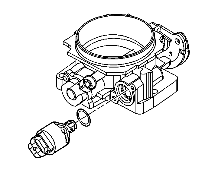
Cleaning and Inspection Procedure
- Clean the IAC valve O-ring sealing surface, the pintle valve seat, and the air passage.
- Inspect the IAC valve O-ring for cuts, cracks, or distortion. Replace if damaged.
| • | Use the carburetor cleaner and a parts cleaning brush in order to remove carbon deposits. Follow instructions on the container. |
| • | Do not use a cleaner that contains methyl ethyl ketone, an extremely strong solvent and not necessary for this type of deposit. |
| • | Shiny spots on the pintle or seat are normal. They do not indicate misalignment or a bent pintle shaft. |
| • | If air passage has heavy deposits, remove the throttle body for a complete cleaning. Refer to Throttle Body Assembly Replacement . |
Installation Procedure
- Measure the distance A between tip of IAC valve pintle and mounting flange.
- Lubricate the IAC valve O-ring with clean engine oil.
- Install the IAC valve assembly.
- Install the attaching fasteners.
- Connect the IAC harness connector.
- Connect negative battery cable.
- Reset the IAC valve pintle position.
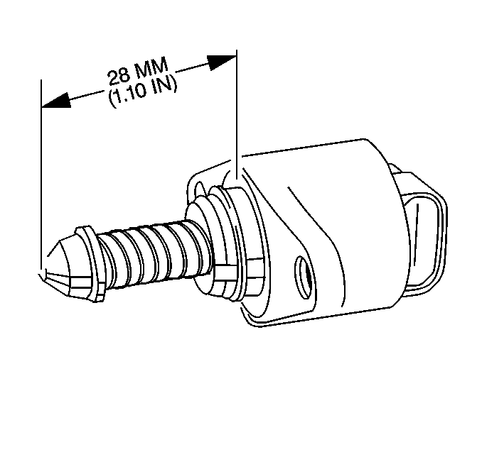
Important: If installing a new IAC valve, replace with an identical part. The IAC valve pintle shape and diameter are designed for the specific application.
If greater than 28 mm, use finger pressure in order to slowly retract the pintle. The force required to retract the pintle of a new valve will not cause damage to the valve.


Notice: Use the correct fastener in the correct location. Replacement fasteners must be the correct part number for that application. Fasteners requiring replacement or fasteners requiring the use of thread locking compound or sealant are identified in the service procedure. Do not use paints, lubricants, or corrosion inhibitors on fasteners or fastener joint surfaces unless specified. These coatings affect fastener torque and joint clamping force and may damage the fastener. Use the correct tightening sequence and specifications when installing fasteners in order to avoid damage to parts and systems.
Tighten
Tighten the IAC valve attaching fasteners to 3.0 N·m (26 lb in).
IAC Valve Reset Procedure
- Turn ON the ignition for 20 seconds.
- Turn OFF the ignition for 10 seconds.
- Start the engine.
- Check for the proper idle speed.
