Steering Column Replacement Comm. w/o I-Beam Front Axle
Removal Procedure
- Set the front wheels in the straight-ahead position.
- Set the steering wheel in the locked position.
- Disconnect the negative battery cable.
- Remove the steering wheel, if required. Refer to Steering Wheel Replacement .
- Disconnect the transmission control linkage from the column. Refer to Shift Cable Replacement in Automatic Transmission.
- Mark the relationship of the upper cardan joint yoke to the steering shaft.
- Remove the upper cardan joint pinch bolt nut from the steering gear coupling shaft.
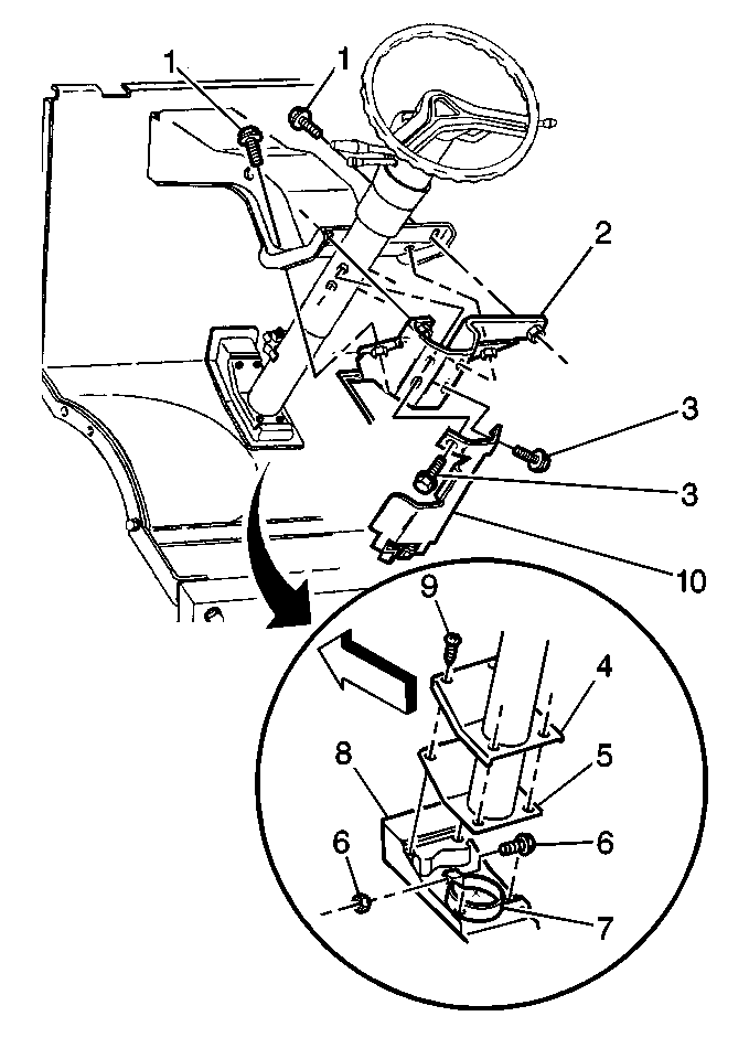
- Remove the upper pinch bolt (3) and the washer.
- Remove the outer steering column support bracket bolts (3).
- Remove the outer support bracket and the inner steering column support bracket bolts (1).
- Remove the inner bracket (2).
- Remove the screws (9) from the cover (4) and the seal (5).
- Remove the nut (6) from the steering column retainer.
- Disconnect the steering column harness at the connectors.
- Remove the steering column assembly. Rotate the column in order to ensure that the shift lever clears the floor opening.
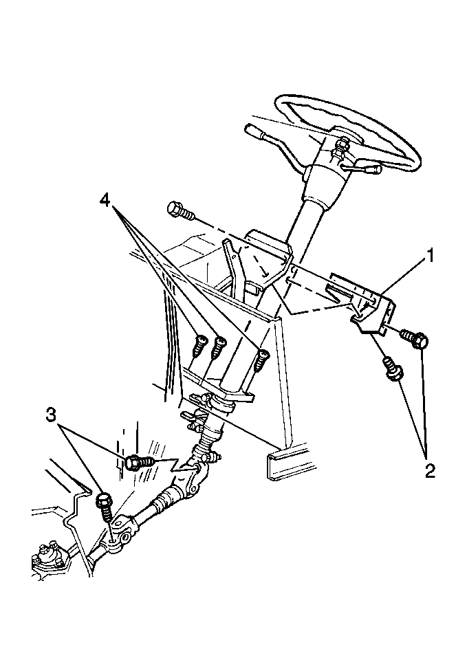
Caution: Unless directed otherwise, the ignition and start switch must be in the OFF or LOCK position, and all electrical loads must be OFF before servicing any electrical component. Disconnect the negative battery cable to prevent an electrical spark should a tool or equipment come in contact with an exposed electrical terminal. Failure to follow these precautions may result in personal injury and/or damage to the vehicle or its components.
Notice: Once the steering column is removed from the vehicle, the column is extremely susceptible to damage. Dropping the column assembly on the end could collapse the steering shaft or loosen the plastic injections, which maintain column rigidity. Leaning on the column assembly could cause the jacket to bend or deform. Any of the above damage could impair the columns collapsible design. Do NOT hammer on the end of the shaft, because hammering could loosen the plastic injections, which maintain column rigidity. If you need to remove the steering wheel, refer to the Steering Wheel Replacement procedure in this section.
Installation Procedure
- Lower the end of the steering column through the floor opening, passing through the loosely positioned floor panel cover (4), the seal (5) , and the retainer (7).
- Guide the steering shaft into the cardan joint yoke by lining up the marks made during the removal.
- Loosely install the inner support bracket (1) and the outer bracket with the bolts.
- Tighten the bolts finger tight.
- Install the upper cardan joint pinch bolt (3) and washer.
- Tighten the steering column inner support bracket (2) bolts.
- Tighten the steering column outer support bracket (10) bolts.
- Secure the steering column with the retainer (7) and bolt (6).
- Install the screws (9) through the cover (4) and the seal (5) to the floor panel.
- Connect the steering column harness.
- Connect the transmission control linkage. Refer to Shift Cable Replacement and Shift Cable Adjustment in Automatic Transmission.
- Install the steering wheel. Refer to Steering Wheel Replacement .
- Connect the negative battery cable.


Notice: Use the correct fastener in the correct location. Replacement fasteners must be the correct part number for that application. Fasteners requiring replacement or fasteners requiring the use of thread locking compound or sealant are identified in the service procedure. Do not use paints, lubricants, or corrosion inhibitors on fasteners or fastener joint surfaces unless specified. These coatings affect fastener torque and joint clamping force and may damage the fastener. Use the correct tightening sequence and specifications when installing fasteners in order to avoid damage to parts and systems.
Ensure that the pinch bolt passes through the shaft undercut.
Tighten
Tighten the pinch bolt nut to 103 N·m (76 lb ft).

Tighten
Tighten the bolts (1) to 25 N·m (18 lb ft).
Tighten
Tighten the bolts (3) to 30 N·m (22 lb ft).
Tighten
Tighten the nut (6) to 15 N·m (11 lb ft).
Tighten
Tighten the screws (9) to 3 N·m (25 lb in).
Steering Column Replacement Comm. with I-Beam Front Axle
Removal Procedure
- Set the front wheels in the straight-ahead position.
- Set the steering wheel in the locked position.
- Disconnect the negative battery cable.
- Remove the steering wheel, if required. Refer to Steering Wheel Replacement .
- Disconnect the transmission control linkage from the column. Refer to Shift Cable Replacement in Automatic Transmission.
- Mark the relationship of the upper cardan joint yoke to the steering shaft.
- Remove the upper cardan joint pinch bolt nut from the steering gear coupling shaft.
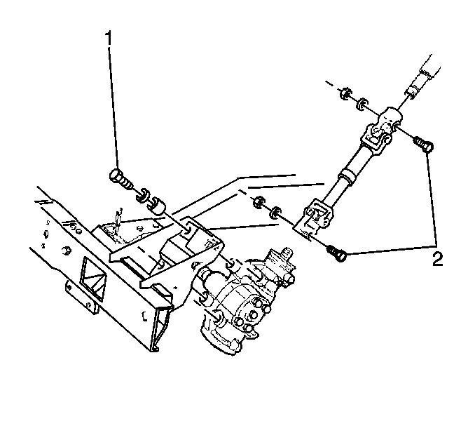
- Remove the upper bolt (2).
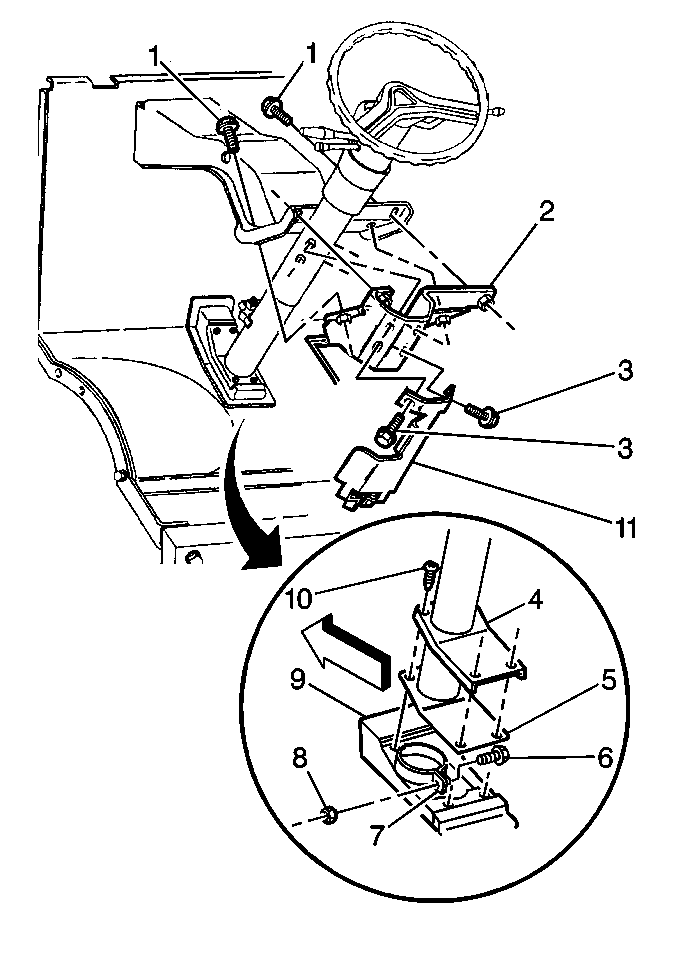
- Remove the bolts (3) from the steering column bracket (11) and the bolts (1) from the inner steering column support bracket (2).
- Remove the screws (10) from the cover (4) and the seal (5).
- Remove the column retainer nut (8).
- Disconnect the steering column harness at the connectors.
- Remove the steering column assembly. Rotate the column so that the shift lever clears the floor opening.
Caution: Unless directed otherwise, the ignition and start switch must be in the OFF or LOCK position, and all electrical loads must be OFF before servicing any electrical component. Disconnect the negative battery cable to prevent an electrical spark should a tool or equipment come in contact with an exposed electrical terminal. Failure to follow these precautions may result in personal injury and/or damage to the vehicle or its components.
Notice: Once the steering column is removed from the vehicle, the column is extremely susceptible to damage. Dropping the column assembly on the end could collapse the steering shaft or loosen the plastic injections, which maintain column rigidity. Leaning on the column assembly could cause the jacket to bend or deform. Any of the above damage could impair the columns collapsible design. Do NOT hammer on the end of the shaft, because hammering could loosen the plastic injections, which maintain column rigidity. If you need to remove the steering wheel, refer to the Steering Wheel Replacement procedure in this section.
Installation Procedure
- Lower the end of the steering column through the floor opening passing through the loosely positioned floor panel cover (4), the seal (5), and the retainer (7).
- Guide the steering shaft into the cardan joint yoke by lining up with the marks made during removal.
- Loosely install the steering column inner support bracket (2) with the bolts (1) and outer bracket (11) with the bolts (3).
- Install the upper cardan joint pinch bolt (2).
- Install the steering column support bracket assembly (2) to the brake pedal bracket assembly with the bolts (1).
- Tighten the steering column outer support bracket bolts (3).
- Secure the steering column retainer (7) with the nut (8) and bolt (6).
- Secure the screws (10) through the cover (4) and the seal (5) to the dash panel.
- Connect the steering column harness.
- Connect the transmission control linkage to the steering column. Refer to Shift Cable Replacement and Shift Cable Adjustment in Automatic Transmission.
- Install the steering wheel if removed. Refer to Steering Wheel Replacement .
- Connect the negative battery cable.

Tighten the bolts finger tight.

Notice: Use the correct fastener in the correct location. Replacement fasteners must be the correct part number for that application. Fasteners requiring replacement or fasteners requiring the use of thread locking compound or sealant are identified in the service procedure. Do not use paints, lubricants, or corrosion inhibitors on fasteners or fastener joint surfaces unless specified. These coatings affect fastener torque and joint clamping force and may damage the fastener. Use the correct tightening sequence and specifications when installing fasteners in order to avoid damage to parts and systems.
Ensure that the pinch bolt passes through the shaft undercut.
Tighten
Tighten the pinch bolt nut to 103 N·m (76 lb ft).

Tighten
Tighten the bolts to 25 N·m (18 lb ft).
Tighten
Tighten the bolts to 30 N·m (22 lb ft).
Tighten
Tighten the nut to 15 N·m (11 lb ft).
Tighten
Tighten the cover screws to 3 N·m (25 lb in).
Steering Column Replacement Motorhome
Removal Procedure
- Set the front wheels in the straight-ahead position.
- Set the steering wheel in the locked position.
- Disconnect the negative battery cable.
- Remove the steering wheel, if required. Refer to Steering Wheel Replacement .
- Disconnect the transmission control linkage from the column. Refer to Shift Cable Replacement in Automatic Transmission.
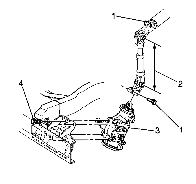
- Mark the relationship of the upper cardan joint yoke to the steering shaft.
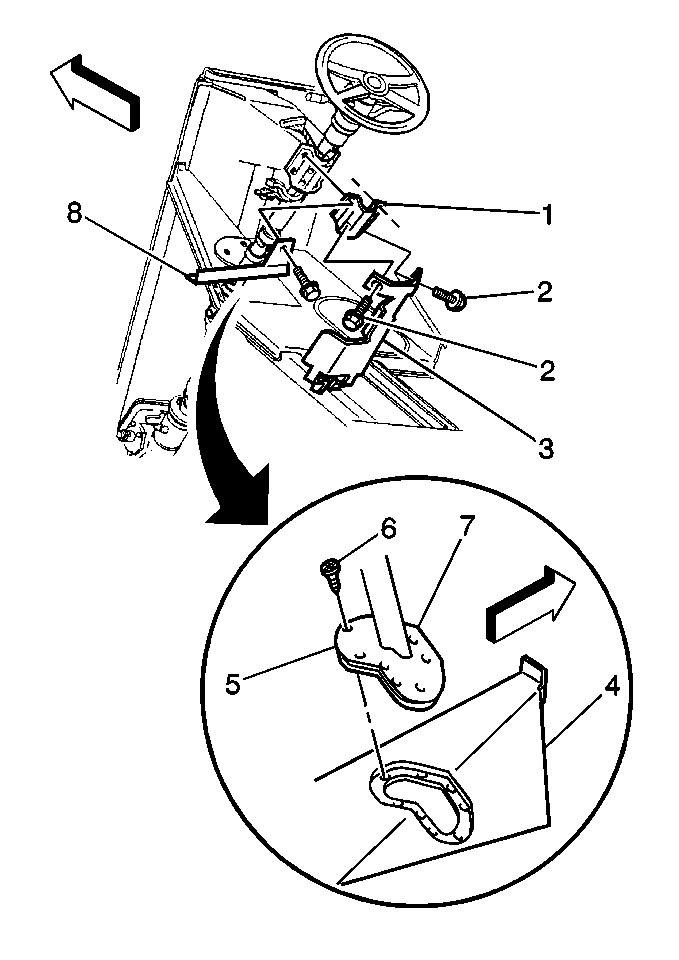
- Remove the upper cardan joint pinch bolt nut from the steering gear coupling shaft and remove the pinch bolt (1).
- Remove the steering column support bracket bolts (2).
- Remove the bracket (3).
- Remove the bolts securing the steering column support bracket (1) including the bolt that secures the parking brake lever brace (8) to the steering column support, or the instrument panel protective cover bracket (for J71 applications).
- Swing the parking brake lever assembly brace, if equipped, away from the steering column. Loosen the left bolt if necessary.
- Remove the screws (6) from the cover (7) and the seal (5) attached to the floor panel (4).
- Disconnect the steering column harness at the connectors.
- Remove the steering column assembly. Rotate the column in order to ensure that the shift lever clears the floor opening.
Caution: Unless directed otherwise, the ignition and start switch must be in the OFF or LOCK position, and all electrical loads must be OFF before servicing any electrical component. Disconnect the negative battery cable to prevent an electrical spark should a tool or equipment come in contact with an exposed electrical terminal. Failure to follow these precautions may result in personal injury and/or damage to the vehicle or its components.
Notice: Once the steering column is removed from the vehicle, the column is extremely susceptible to damage. Dropping the column assembly on the end could collapse the steering shaft or loosen the plastic injections, which maintain column rigidity. Leaning on the column assembly could cause the jacket to bend or deform. Any of the above damage could impair the columns collapsible design. Do NOT hammer on the end of the shaft, because hammering could loosen the plastic injections, which maintain column rigidity. If you need to remove the steering wheel, refer to the Steering Wheel Replacement procedure in this section.
Installation Procedure
- Lower the end of the steering column through the floor opening and through the loosely positioned seal (5) and cover (7).
- Guide the steering shaft into the cardan joint yoke by lining up the marks made during removal.
- Loosely secure the steering column support bracket (1) with the parking brake lever brace (8), if equipped, or the instrument panel protective cover bracket (for J71 applications), and the outer bracket (3) with the bolts (2).
- Install the upper cardan joint pinch bolt (1).
- Tighten the steering column brackets bolts.
- Install the screws (6) through the cover (7) and the seal (5) to the floor panel (4).
- Connect the steering column harness.
- Connect and adjust the transmission control linkage. Refer to Shift Cable Replacement and Shift Cable Adjustment in Automatic Transmission.
- Install the steering wheel, if removed. Refer to Steering Wheel Replacement .
- Connect the negative battery cable.

Tighten the bolts finger tight.

Notice: Use the correct fastener in the correct location. Replacement fasteners must be the correct part number for that application. Fasteners requiring replacement or fasteners requiring the use of thread locking compound or sealant are identified in the service procedure. Do not use paints, lubricants, or corrosion inhibitors on fasteners or fastener joint surfaces unless specified. These coatings affect fastener torque and joint clamping force and may damage the fastener. Use the correct tightening sequence and specifications when installing fasteners in order to avoid damage to parts and systems.
Ensure that the pinch bolt passes through the shaft undercut.
Tighten
Tighten the pinch bolt nut to 45 N·m (33 lb ft).

Tighten
Tighten the bolts to 30 N·m (22 lb ft).
Tighten
Tighten the screws to 5 N·m (42 lb in).
