Compressor P72
Removal Procedure
- Discharge and recover the refrigerant from the system. Refer to Refrigerant Recovery and Recharging .
- Disconnect the negative battery cable. Refer to
Caution: Unless directed otherwise, the ignition and start switch must be in the OFF or LOCK position, and all electrical loads must be OFF before servicing any electrical component. Disconnect the negative battery cable to prevent an electrical spark should a tool or equipment come in contact with an exposed electrical terminal. Failure to follow these precautions may result in personal injury and/or damage to the vehicle or its components.
in General Information. - Disconnect the electrical connector to the magnetic drive clutch.
- Remove the accessory drive belt from the compressor pulley. Refer to Accessory Drive Belt in Engine Mechanical.
- Disconnect the refrigerant hose assemblies from the compressor.
- Cap or plug all open connections.
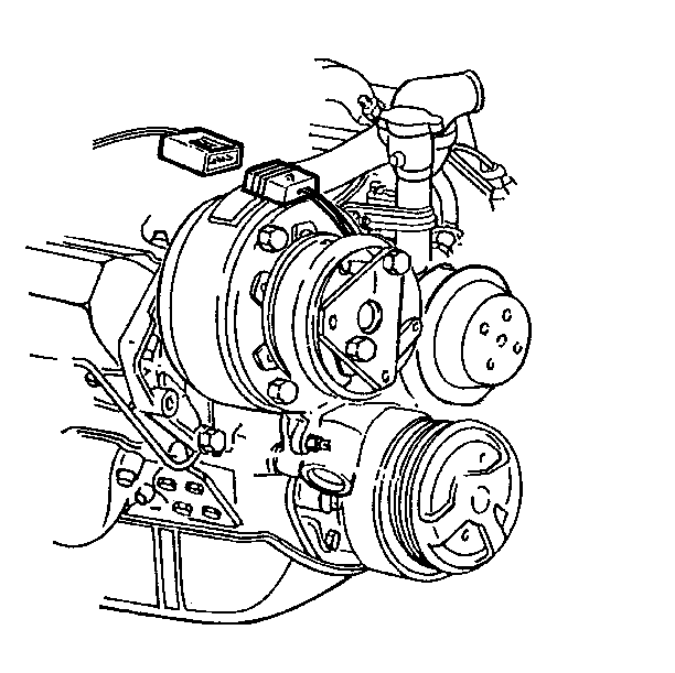
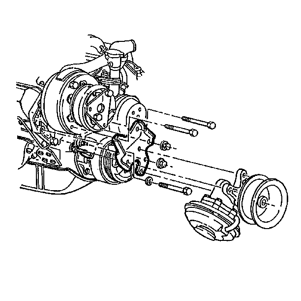
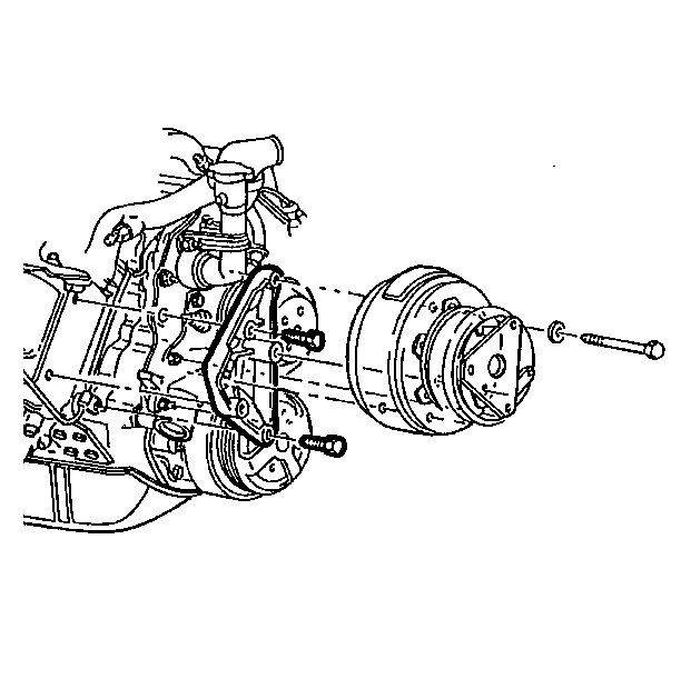
- Remove the short mounting bolts and the nuts.
- Remove the vacuum pump.
- Drain the long compressor mounting bolts, the washers and the vacuum pump mounting bracket.
- Remove the bolt that secures the compressor to the compressor mounting bracket.
- Remove the bracket mounting bolts. Remove the compressor mounting bracket.
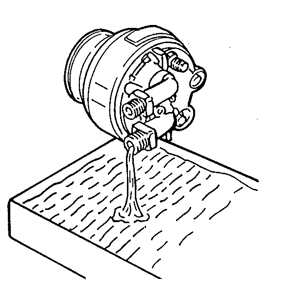
- Drain the oil from the compressor though the connectors and the oil drain hole.
- Check the quantity and the amount of contamination of the oil drained from the compressor.
Installation Procedure
- Install 236 ml (8 fl oz) of oil in the Harrison compressor.
- Use the bracket mounting bolts to install the compressor mounting bracket onto the engine.
- Install the bolt which secures the compressor to the compressor mounting bracket.
- Install the compressor on the mounting bracket.
- Install the vacuum pump mounting bracket on the compressor using the washers, the long mounting bolts and the nuts.
- Using the short bolts, install the vacuum pump on the mounting bracket.
- Connect the refrigerant hoses to the compressor.
- Install the accessory drive belt over the pulley. Refer to Accessory Drive Belt in Engine Mechanical.
- Evacuate the air from the system and charge with refrigerant. Refer to Refrigerant Recovery and Recharging or the coach manufacturer's service manual.

Notice: Use the correct fastener in the correct location. Replacement fasteners must be the correct part number for that application. Fasteners requiring replacement or fasteners requiring the use of thread locking compound or sealant are identified in the service procedure. Do not use paints, lubricants, or corrosion inhibitors on fasteners or fastener joint surfaces unless specified. These coatings affect fastener torque and joint clamping force and may damage the fastener. Use the correct tightening sequence and specifications when installing fasteners in order to avoid damage to parts and systems.

Compressor P92
Removal Procedure
- If the compressor is operational, perform the oil return procedure. Refer to Oil Return Procedure .
- Discharge and recover refrigerant from the system. Refer to Refrigerant Recovery and Recharging .
- Disconnect the negative battery cable. Refer to
Caution: Unless directed otherwise, the ignition and start switch must be in the OFF or LOCK position, and all electrical loads must be OFF before servicing any electrical component. Disconnect the negative battery cable to prevent an electrical spark should a tool or equipment come in contact with an exposed electrical terminal. Failure to follow these precautions may result in personal injury and/or damage to the vehicle or its components.
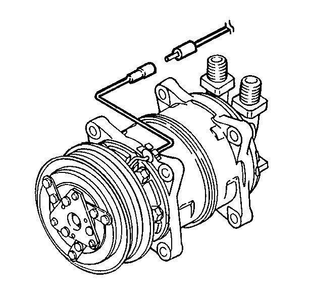
in General Information. - Disconnect the electrical connector from the magnetic drive clutch.
- Remove the accessory drive belt from the compressor pulley. Refer to Accesssory Drive Belt Replacement in Engine Mechanical.
- Disconnect the refrigerant hose assemblies from the compressor. Cap or plug all open connections.
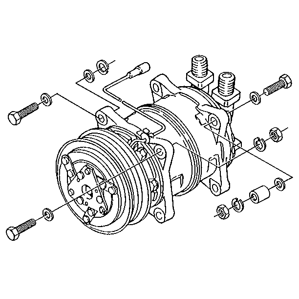
- Remove the bolts, the washers, the lockwashers, the spacers, and the nuts.
- Remove the compressor from the engine.
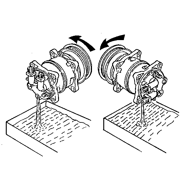
- Drain the oil from the compressor through the connectors and the oil drain hole.
- Check the quantity and the amount of contamination of the oil that was drained from the compressor.
Installation Procedure
- New compressors are filled with compressor oil and N2 gas. Perform the following steps when you install a new compressor:
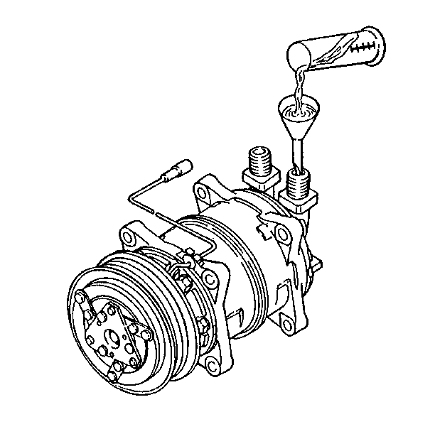
- Pour the oil into the compressor. The quantity of oil you should use is shown on the information plate attached to the compressor housing.
- Install the compressor on the engine.
- Install the bolts, the washers, the lockwashers and the spacers.
- Connect the refrigerant hoses to the compressor.
- Install the accessory drive belt over the pulley. Refer to Accessory Drive Belt Replacement in Engine Mechanical.
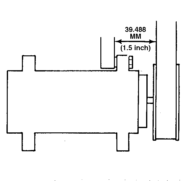
- Measure the distance from the upper compressor mounting bracket to the accessory drive belt. The distance must be 39.488 mm (1.55 in) in order for the pulley to be aligned properly.
- Connect the electrical wires to the magnetic drive clutch.
- Evacuate air from the system and charge with refrigerant. Refer to Refrigerant Recovery and Recharging or the coach manufacturer's service manual.
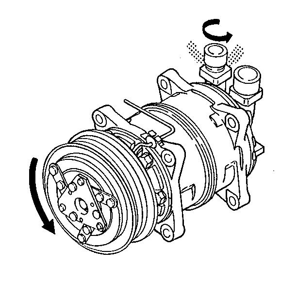
| 1.1. | Loosen the discharge-side connector's cap and gently release N2 from the compressor. Do not release compressor oil. |
| 1.2. | Slowly rotate the compressor's magnetic clutch several times by hand in order to distribute the oil which has settled in the cylinders. |

Notice: Use the correct fastener in the correct location. Replacement fasteners must be the correct part number for that application. Fasteners requiring replacement or fasteners requiring the use of thread locking compound or sealant are identified in the service procedure. Do not use paints, lubricants, or corrosion inhibitors on fasteners or fastener joint surfaces unless specified. These coatings affect fastener torque and joint clamping force and may damage the fastener. Use the correct tightening sequence and specifications when installing fasteners in order to avoid damage to parts and systems.
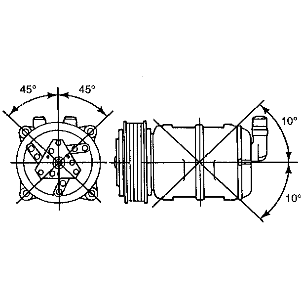
Important: Due to the pressure feed lubrication system, the compressor must be mounted within 45 degrees vertically and 10 degrees horizontally of an upright position. Ensure that the compressor is upright when you install it.
