For 1990-2009 cars only
Removal Procedure
Tools Required
| • | J 25031 Rotor and Bearing Puller |
| • | J 8433 Speedometer Gear Puller |
| • | J 24092 Clutch Coil Puller Legs |
| • | J 25287 Clutch Coil Puller |
- Remove the clutch plate and hub assembly. Refer to Compressor Clutch Plate and Hub Assembly .
- Remove the pulley rotor and bearing assembly. Refer to Clutch Rotor and/or Bearing .
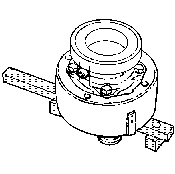
- Mark the location of the clutch coil terminals on the compressor.
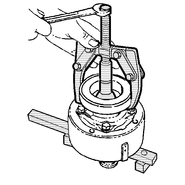
- Install the J 25031 to the front head.
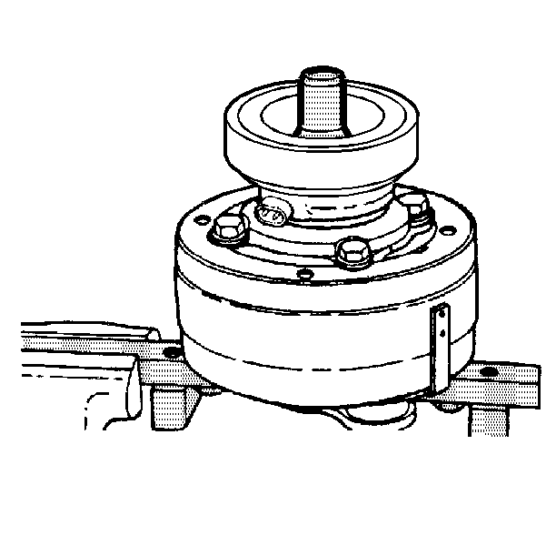
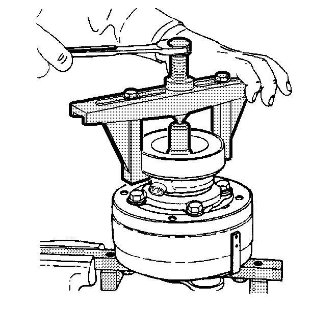
- Install the J 8433 with the J 24092 .
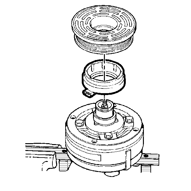
- Remove the clutch coil from the front head.
- The clutch coil can also be removed by using the J 25031 with the J 25287 .
Installation Procedure
Tools Required
J 26271-A Rotor and Bearing Assembly Installer
- Place the clutch coil assembly on the neck of the front head.
- Place the rotor and bearing assembly on the neck of the front head.
- Use the J 26271-A in order to seat the clutch coil and the pulley rotor in place.
- Install the rotor and bearing assembly. Refer to Clutch Rotor and/or Bearing .
- Install the clutch plate and hub assembly. Refer to Compressor Clutch Plate and Hub Assembly Removal . Ensure that the air gap between the clutch plate and the clutch rotor is 0.4-0.5 mm (0.15-0.20 in).
Important: Ensure that the clutch coil terminals are in line with the mark made during removal.

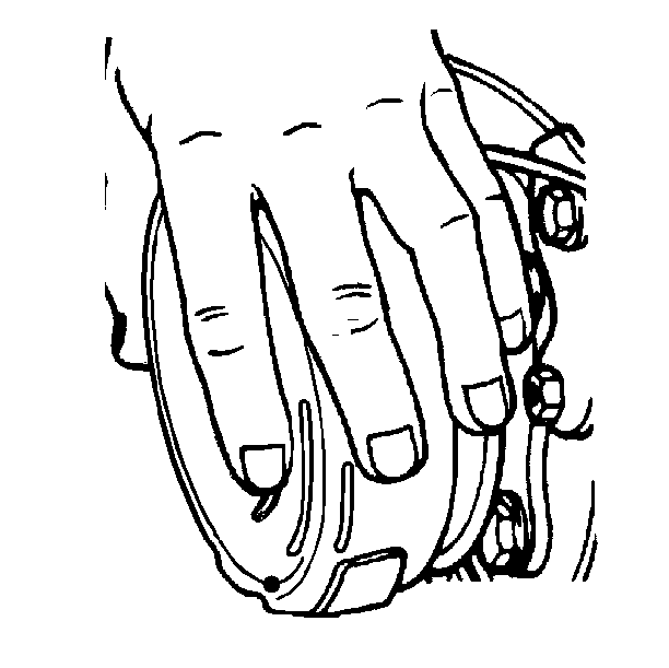
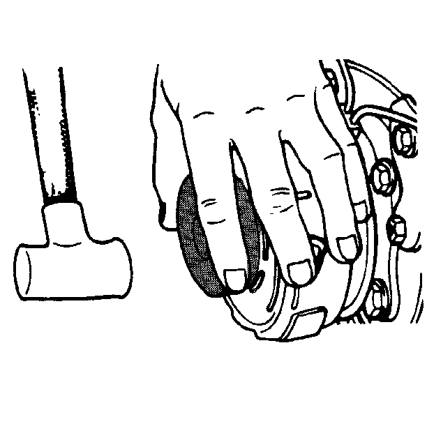
| • | Ensure that the clutch coil terminals are properly located in relation to the compressor. |
| • | Ensure that the three protrusions on the rear of the clutch coil housing aligns with the locator holes in the front head. |
