Compressor Magnetic Clutch Seltec TM-16HD
Removal Procedure
- Disconnect the negative battery cable. Refer to
Caution: Unless directed otherwise, the ignition and start switch must be in the OFF or LOCK position, and all electrical loads must be OFF before servicing
any electrical component. Disconnect the negative battery cable to prevent an electrical spark should a tool or equipment come in contact with an exposed electrical terminal. Failure to follow these precautions may result in personal injury and/or damage to
the vehicle or its components.
in General Information.
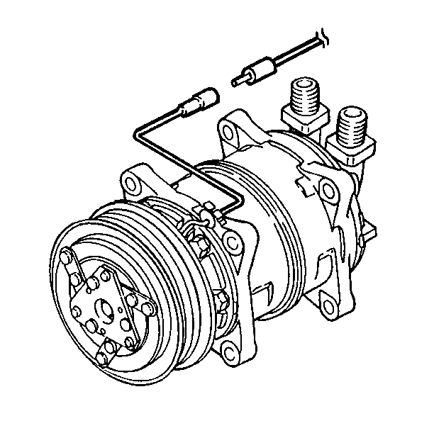
- Disconnect the electrical connector to
the magnetic drive clutch.
- Remove the compressor from the engine.
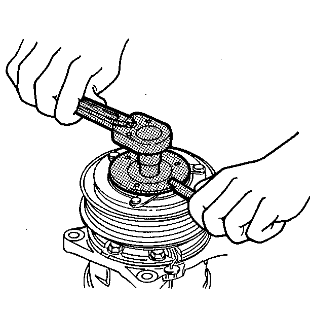
- Remove the center armature bolt using the armature plate holder
to prevent armature plate rotation.
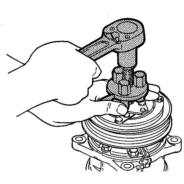
- Remove the armature plate using the armature
plate puller.
- Remove the shims from the armature shaft
or the armature plate. Retain the shims.
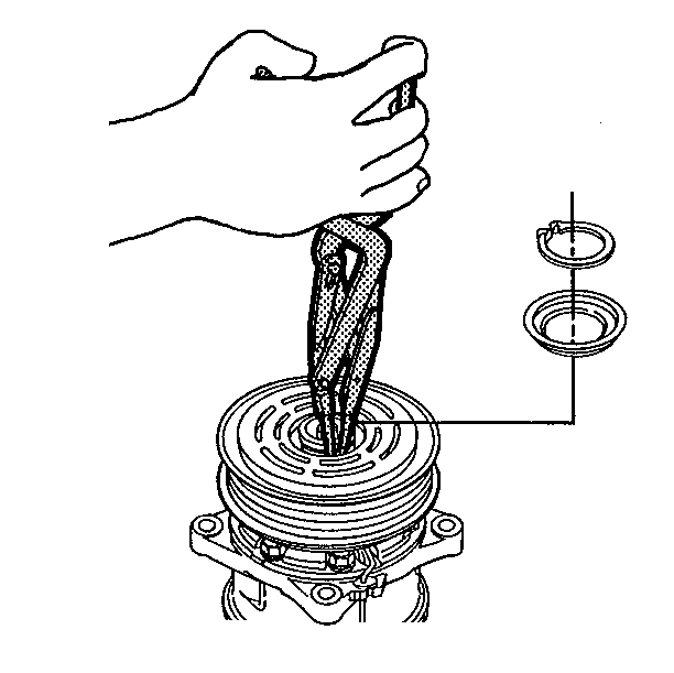
- Remove the snap ring and cover using the external snap ring pliers.
NOTICE: To avoid damaging the pulley, the puller arms should be hooked into,
not under, the pulley groove.
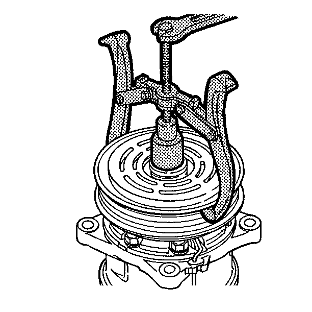
- Remove the pulley assembly using the pulley
puller and the spacer in the cylinder hub.
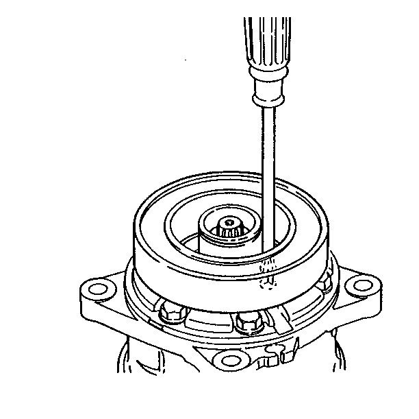
- Remove the coil leadwire from the wire
holder on the compressor.
- Remove the three screws.
- Remove the coil. Do not allow the coil to dangle from the lead
wires.
Inspection Procedure
| • |
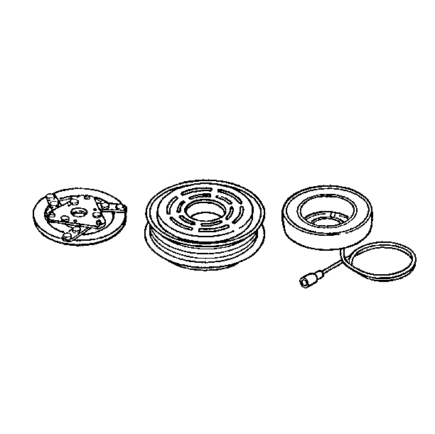
Inspect the armature plate for a scorched
surface. If the surface shows evidence of scorching, replace the armature
plate and pulley. |
| • | Inspect the pulley assembly contact surface for grooves resulting
from slippage. Ensure there is no foreign matter lodged between the clutch
plate and the pulley. If the pulley contact surface is excessively grooved,
both the pulley and the armature plate must be replaced. |
| • | Inspect the coil for a loose connector or cracked insulation.
If the connector is loose or the insulation is cracked, the coil must be replaced. |
Installation Procedure
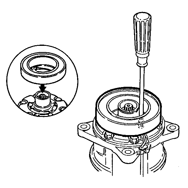
- Install the three screws to secure the
coil on the compressor.
Tighten
Tighten the screws to 4-6 N·m (34.8-51.6 lb in).
Refer to
Notice: Use the correct fastener in the correct location. Replacement fasteners
must be the correct part number for that application. Fasteners requiring
replacement or fasteners requiring the use of thread locking compound or sealant
are identified in the service procedure. Do not use paints, lubricants, or
corrosion inhibitors on fasteners or fastener joint surfaces unless specified.
These coatings affect fastener torque and joint clamping force and may damage
the fastener. Use the correct tightening sequence and specifications when
installing fasteners in order to avoid damage to parts and systems.
in General
Information.- Install the wire lead into the wire holder on the compressor.
- Install the pulley assembly using the proper installer and a hand
press.
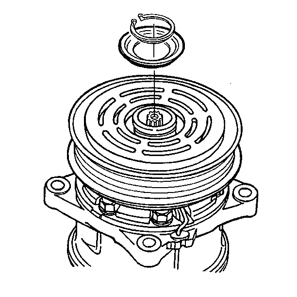
- Install the cover and the snap ring. When
you install the snap ring, the chamfered inner edge of the snap ring should
face upward.
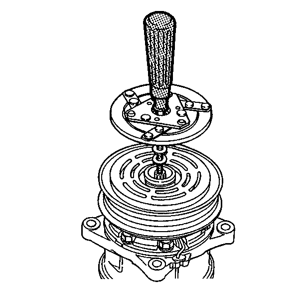
- Install the original shims on the drive
shaft.
- Press the armature plate onto the armature shaft by hand.
- Install the center armature bolt.
Tighten
Tighten the center armature bolt to 12-14 N·m (8.7-10.1 lb ft).
- Ensure that the pulley rotates smoothly.
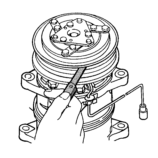
- Measure the clutch clearance. The measurement
should be 0.3-0.6 mm (0.01-0.02 in). Add or subtract
shims to achieve proper clearance.
- Install the compressor on the engine.

- Connect the electrical connector to the
magnetic drive clutch.
- Connect the negative battery cable.
- Perform the Magnetic Clutch Run-In.
| 13.2. | Operate the air conditioning system. |
| 13.3. | Operate the air conditioning ON/OFF switch, on for 10 seconds,
then off for 10 seconds. Repeat this procedure 10 times. |


