Lower Control Arm Ball Joint Replacement RWD
Removal Procedure
For control arms and components, refer to
Control Arm and Components (2WD)
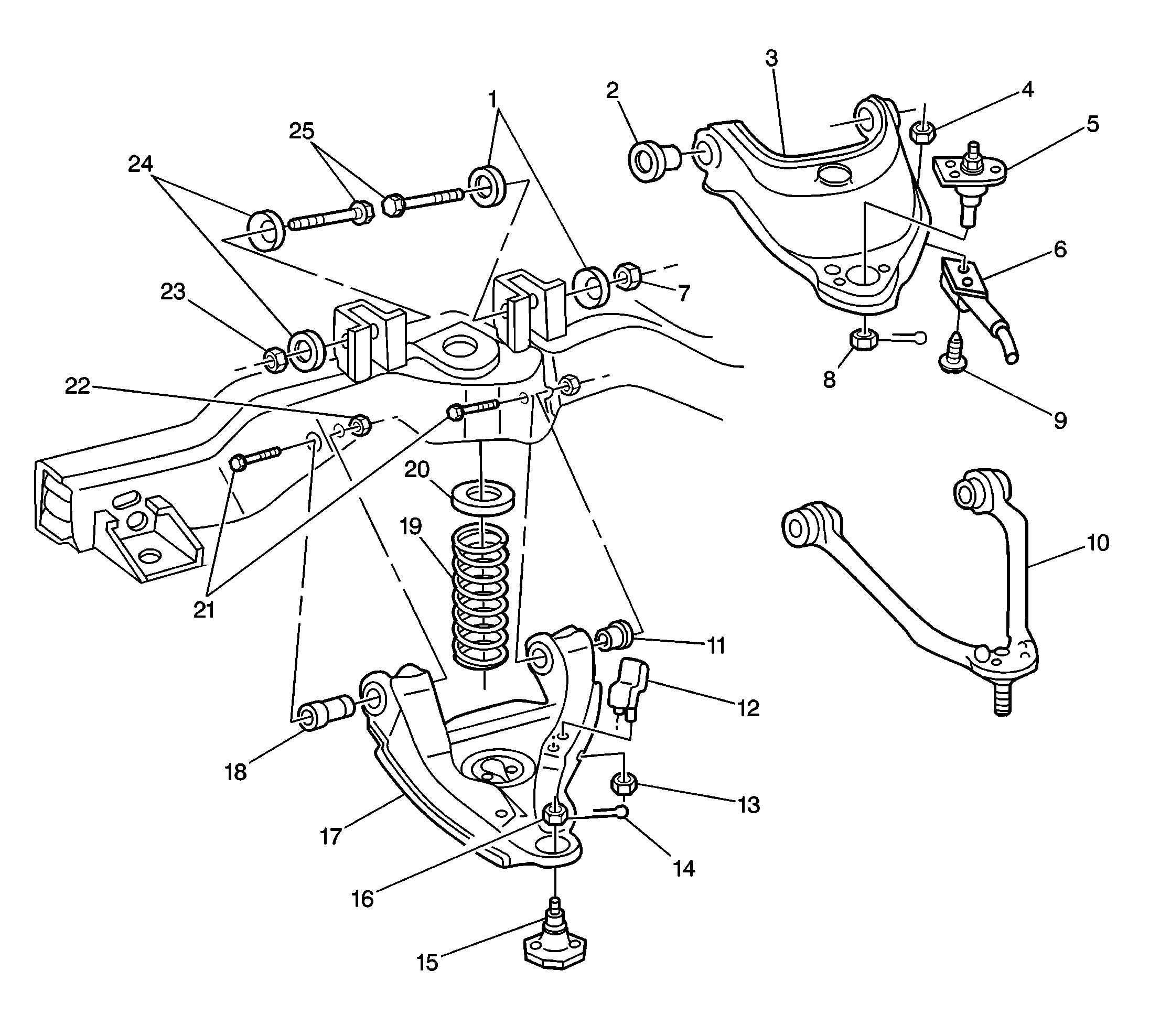
Tools Required
| • | J 9519-D Ball
Joint Remover and Installer Set |
- Raise the vehicle. Support the frame with safety stands.
- Remove the tire and wheel assembly. Refer to
Wheel Removal
in Tires and Wheels.
Caution: Floor jack must remain under the lower control arm during
removal and installation to retain the lower control arm in position. Failure
to do so could result in personal injury.
- Place a floor jack under the control arm spring seat. Raise the jack
in order to support the control arm.
Notice: Support the caliper with a piece of wire to prevent damage to the brake
line.
- Remove the brake caliper. Refer to
Brake Caliper Replacement
in Disc Brakes.
- Remove the cotter pin and the nut.
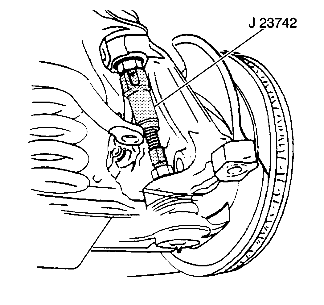
- Break the ball joint loose
from the knuckle using the J 23742
.
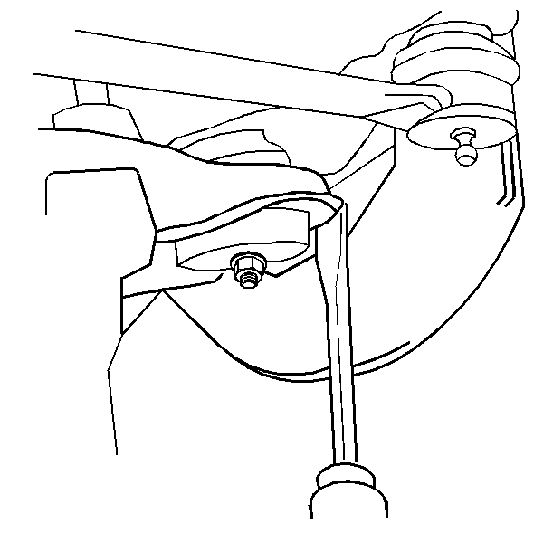
Important: Place a wooden block between the frame and the upper control arm in
order to block the knuckle assembly out of the way.
- Remove the lower control arm from the knuckle. Guide the lower control
arm out of the splash shield with a screwdriver while lifting the upper control
arm with a pry bar.
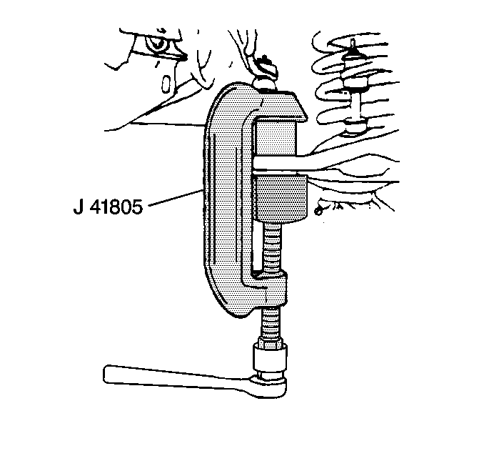
- Remove the lower ball
joint from the lower control arm using the tools as shown.
- Inspect the tapered hole in the steering knuckle. Remove any dirt.
If the tapered hole is out of round, deformed or damaged, replace the knuckle.
Installation Procedure
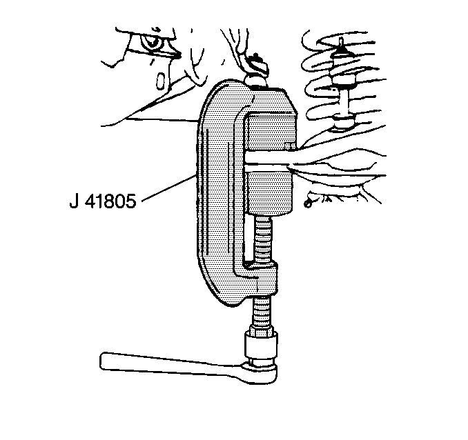
- Install a new ball joint
into the lower control arm.
| 1.1. | Press in the ball joint using the tools as shown. |
| 1.2. | The ball joint will bottom on the control arm. |
- Install the ball joint stud into the steering knuckle.
Notice: Use the correct fastener in the correct location. Replacement fasteners
must be the correct part number for that application. Fasteners requiring
replacement or fasteners requiring the use of thread locking compound or sealant
are identified in the service procedure. Do not use paints, lubricants, or
corrosion inhibitors on fasteners or fastener joint surfaces unless specified.
These coatings affect fastener torque and joint clamping force and may damage
the fastener. Use the correct tightening sequence and specifications when
installing fasteners in order to avoid damage to parts and systems.
- Install the stud
nut onto the stud.
Tighten
Tighten the nut to 128 N·m (94 lb ft). Tighten
in order to align the slot in the stud nut with the hole in the stud.
- Install a new cotter pin to the stud.
- Install the brake caliper. Refer to
Brake Caliper Replacement
in Disc Brakes.
- Install the tire and wheel assembly. Refer to
Wheel Installation
in Tires and Wheels.
- Lower the vehicle.
- Check the front wheel alignment. Refer to
Wheel Alignment Measurement
in Wheel Alignment.
Lower Control Arm Ball Joint Replacement S4WD
Removal Procedure
Tools Required
| • | J 39549 Ball Joint/Tie Rod
End Separator |
| • | J 9519-E Ball Joint
Remover/Installer Set |
| • | J 41435 Ball Joint
Remover and Installer Kit, consisting of: J 41435-1, 2, 3 |
| • | J 29193 Steering Linkage
Installer |
- Raise the vehicle. Support the vehicle with suitable safety stands.
- Remove the tire and wheel assembly. Refer to
Wheel Removal
in Tires and Wheels.
Caution: Floor jack must remain under the lower control arm during
removal and installation to retain the lower control arm in position. Failure
to do so could result in personal injury.
- Place a floor jack under the control arm. Raise the jack until the jack supports
the control arm.
- Remove the halfshaft. Refer to
Wheel Drive Shaft Replacement
in Wheel Drive Shafts.
Notice: Support the caliper with a piece of wire to prevent damage to the brake
line.
- Remove the brake caliper. Refer to
Brake Caliper Replacement
in Disc Brakes.
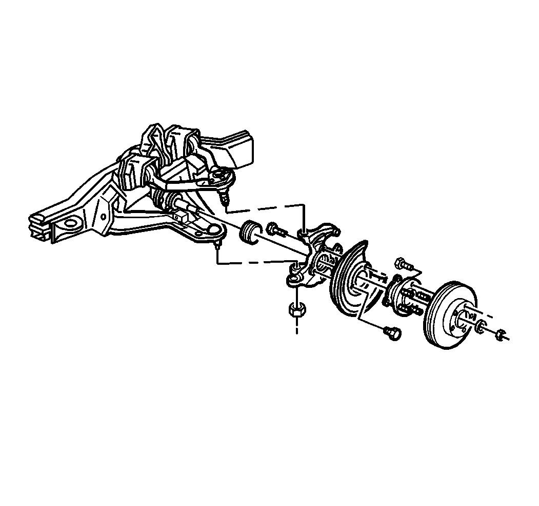
- Remove the cotter pin and the nut from the
lower control arm ball joint.
- Using J 39549
, break the
ball joint loose from the knuckle.
- Remove the lower control arm from the knuckle.
- Remove the knuckle from the vehicle.
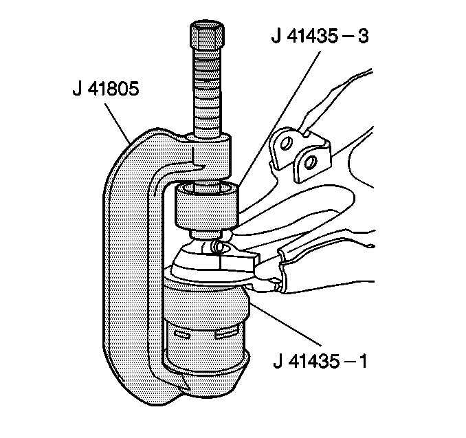
- Remove the ball joint from the lower control
arm. Use the tools as shown.
- Inspect the tapered hole in the steering knuckle and remove any dirt.
If this hole is out of round, deformed, or damaged, replace the knuckle.
Installation Procedure
- Clean the mounting surfaces of the lower control arm ball joint and the
new ball joint with denatured alcohol or the equivalent prior to installation.
Do not apply solvent to the ball joint seal.
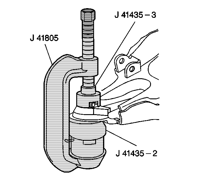
- Install the new ball joint into the lower
control arm.
| 2.1. | Apply a 6 mm (¼ in) bead of LOCTITE® 680 or the
equivalent evenly to the serrations on the ball joint prior to installation. |
| 2.2. | Position the ball joint in the control arm with the grease fitting toward
the rear of the vehicle. |
| 2.3. | Press in the ball joint using the tools as shown. |
| • | The ball joint will bottom on the control arm. |
| • | When installing the ball joint with the J 41435
, make sure the notch in the tool aligns with the grease fitting. |

- Install the ball joint into the steering
knuckle.
Notice: Refer to Fastener Notice in the Preface section.
- Install the stud nut onto the stud.
Tighten
Tighten the nut to 128 N·m (94 lb ft).
Tighten in order to align the slot in the stud nut with the hole in the stud.
- Install a new cotter pin to the stud.
- Install the halfshaft. Refer to
Wheel Drive Shaft Replacement
in Wheel Drive Shafts.
- Install the brake caliper. Refer to
Brake Caliper Replacement
in Disc Brakes.
- Install the tire and wheel assembly. Refer to
Wheel Installation
in Tires and Wheels.
Important: Check the front wheel alignment. Refer to
Wheel Alignment Measurement
in Wheel Alignment.
- Lower the vehicle.


