Brake Lining Replacement Duo-Servo Drum Brakes
Removal Procedure
GM replacement brake lining material is recommended for all vehicles to maintain the balance between front and rear brake performance. GM replacement brake parts have been carefully selected to provide the proper brake balance for the purposes of stopping distance and control over the full range of operating conditions. Installation of front or rear lining material with performance different from that of GM replacement parts recommended for this vehicle can change the intended brake balance of this vehicle.
- Raise the vehicle and support the vehicle with safety stands.
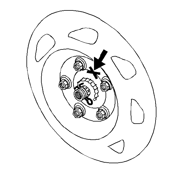
- Mark the relationship of the wheel to the hub.
- Remove the tire.
- Remove the wheel. Refer Wheel Removal in Tires and Wheels.
- Mark the relationship of the drum to the axle.
- Remove the drum.
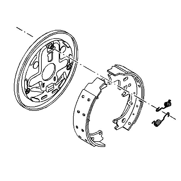
- Remove the return springs.
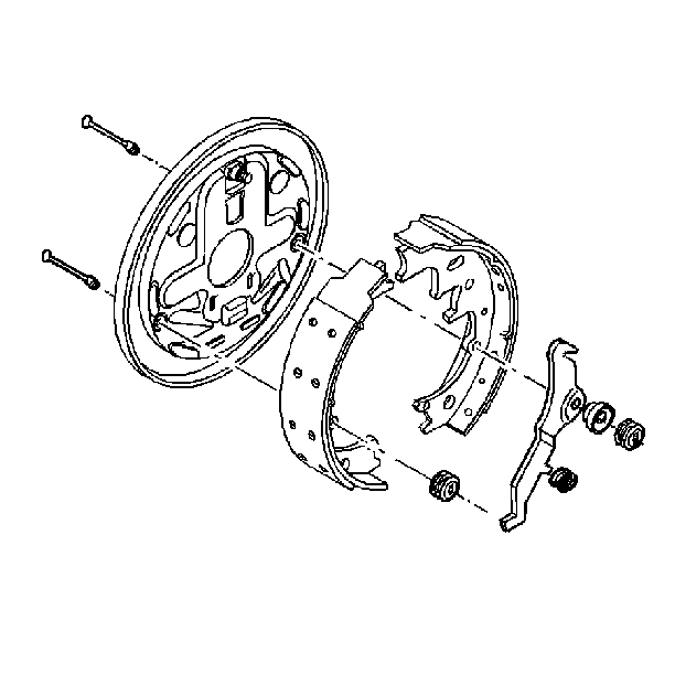
- Remove the shoe guide.
- Remove the hold down springs.
- Remove the hold down pins.
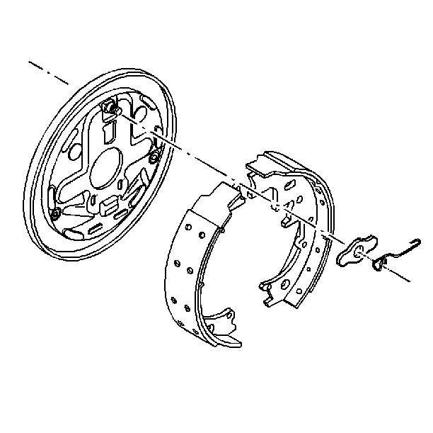
- Disconnect the actuator lever and the lever pivot.
- Remove the lever return spring.
- Remove the actuator link.
- Disconnect the parking brake strut and the strut spring.
- Remove the parking brake lever.
- Remove the adjusting screw assembly.
- Remove the screw spring.
- Inspect all parts for discoloration due to heat or stress. Replace as needed.
- Inspect all parts for signs of wear. Replace as needed.
- Inspect the wheel cylinder for signs of leakage. Refer to Wheel Cylinder Replacement .
- Inspect the brake drum for scoring and machining tolerance. Refer to Brake Drum Inspection .
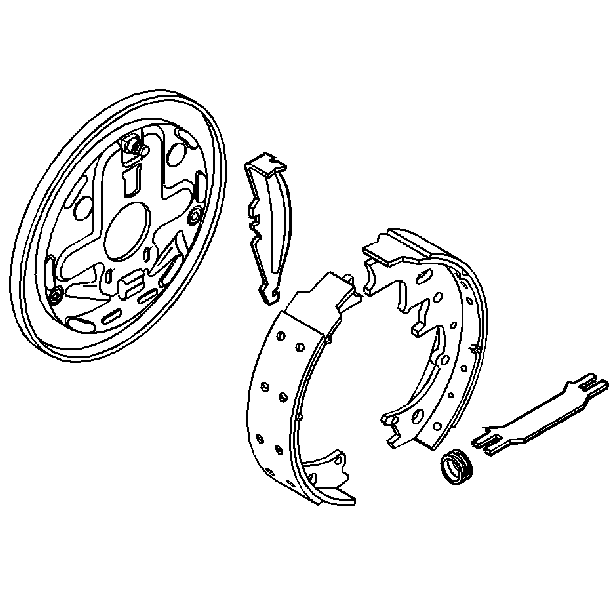
Installation Procedure
- Lubricate the shoe pads and adjusting screw threads with a thin coat of white lithium grease or equivalent.
- Install the adjusting screw assembly and the adjusting screw spring to both shoes. The coils of the adjusting screw spring must not touch the adjusting screw.
- Connect the shoe assembly to the backing plate.
- Install the parking brake lever.
- Install the strut spring onto the parking brake strut.
- Install the parking brake strut.
- Connect the actuator lever and the lever pivot.
- Install the actuator link.
- Install the lever return spring.
- Install the hold down pins.
- Install the hold down springs.
- Install the shoe guide.
- Install the return springs.
- Install the drum. Align the marks made during disassembly.
- Install the tire and the wheel. Refer to Wheel Installation in Tires and Wheels. Align the marks made during disassembly.
- Adjust the rear brakes. Refer to Drum Brake Adjustment .
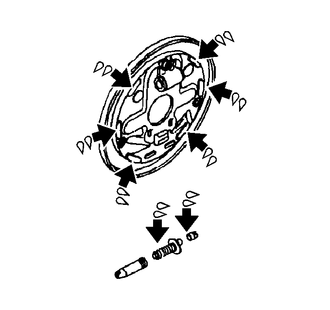
Important: Do not interchange the right and the left adjusting screws.
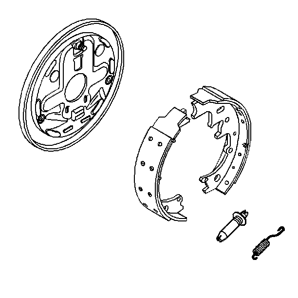


Brake Lining Replacement Leading/Trailing Drum Brakes
Removal Procedure
GM replacement brake lining material is recommended for all vehicles to maintain the balance between front and rear brake performance. GM replacement brake parts have been carefully selected to provide the proper brake balance for the purposes of stopping distance and control over the full range of operating conditions. Installation of front or rear lining material with performance different from that of recommended GM replacement parts can change the intended brake balance of this vehicle.
- Raise the vehicle and support the vehicle with safety stands.
- Mark the relationship of the wheel to the hub.
- Remove the tire and the wheel. Refer to Wheel Removal in Tires and Wheels.
- Mark the relationship of the drum to the axle.
- Remove the drum. Refer to Hub and Drum Assembly Replacement in Rear Axle.
- If the drum is difficult to remove, do the following:
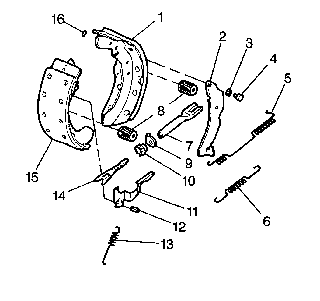
- Remove the actuator spring and the adjuster actuator.
- Raise the lever arm of the actuator until the upper end is clear of the slot in the adjuster screw.
- Slide the actuator (10) off of the adjuster pin (12).
- Disconnect the actuator spring (13) from the shoe (15).
- Remove the hold-down spring assemblies (8) and the pins.
- Remove the lower return spring (6).
- Remove the shoe and lining assemblies (1 and 15).
- Remove the upper return spring (5).
- Remove the adjusting screw assembly.
- Remove the upper return spring (5).
- Remove the adjusting screw assembly from the shoes.
- Remove the retaining ring (16).
- Remove the pin (14).
- Remove the spring washer (3).
- Remove the parking brake lever (2).
- Inspect the wheel cylinder for signs of leakage. Refer to Wheel Cylinder Replacement .
- Inspect the brake drum for signs of scoring and machining tolerance. Refer to Brake Drum Inspection .
- Replace any parts that show signs of discoloration from heat, stress, or wear.
- Inspect the threads of the adjuster screw (14) for smooth rotation over the full length.
- Using denatured alcohol, clean the following components:
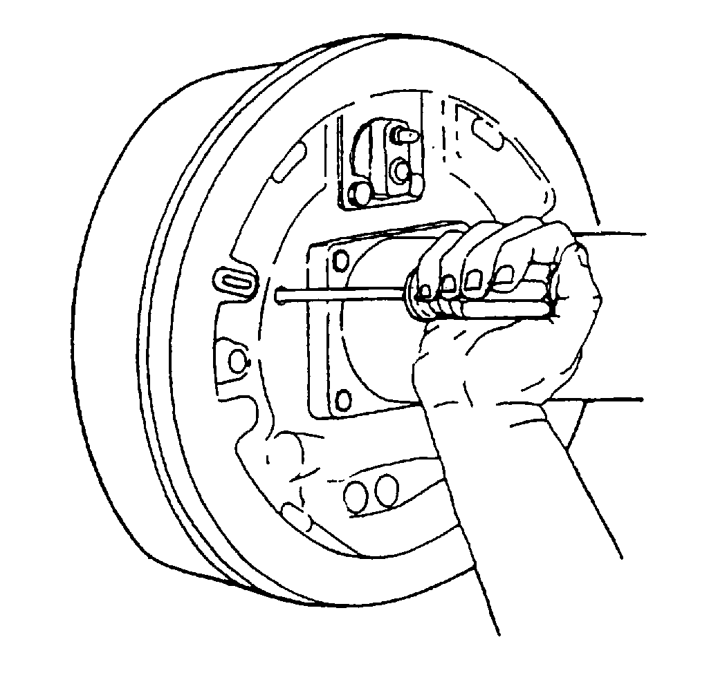
| • | Make sure the parking brake is released. |
| • | Back off the parking brake cable adjustment. |
| • | Remove the access hole plug from the backing plate and insert a screwdriver through the hole to push the parking brake lever off the stop. |
| • | Use a rubber mallet to tap gently on the outer rim of the drum and/or around the inner drum diameter. Be careful to not deform the drum by excessive beating. |
| • | Pull the bottom ends of the shoes apart. |
| • | Lift the lower return spring (6) over the anchor plate. |
| • | Allow the shoe ends to come together. |
| • | Release the spring. |
| • | Do not damage the wheel cylinder boots. |
| • | Bring the bottom ends of the shoes together (overlap if necessary) so the upper shoe ends clear the wheel cylinder boots. |
| • | Spread the bottom of the assembly to clear the axle flange. |

| • | The adjuster screw (14) |
| • | The nut (10) |
| • | The spring clip (9) |
| • | The adjuster socket (7) |
Installation Procedure
- Install the parking brake lever (2).
- Install the spring washer (3). The concave side of the spring washer should face the parking brake lever.
- Install the pin (4).
- Install the retaining ring (16).
- Install the adjuster pin (12) in the shoe (15) so the pin projects 6.8 to 7.0 mm (0.268 to 0.276 in) from the side of the shoe web where the adjuster actuator is installed.
- Apply brake lubricant GM P/N 5450032 or equivalent to the threads of the adjuster screw (14) and inside diameter and face of the socket (7). Adequate lubrication is achieved when there is a continuous bead of lubricant at the open end of the adjuster nut (10) and the socket (7) when the threads are fully engaged.
- Install the upper return spring (5).
- Install the adjusting screw assembly.
- Lubricate the shoe pads on the backing plate with a thin coat of white lithium grease.
- Install the shoe and lining assemblies (1 and 15).
- Install the upper return spring (5).
- Install the adjusting screw assembly.
- Install the lower return spring (6).
- Connect the hold-down pins and the spring assemblies (8).
- Install the adjuster actuator (11) over the end of the adjuster pin (12) so the top leg engages the notch in the adjuster screw.
- Install the actuator spring (13). The free end of the adjuster actuator (11) must engage the notch of the adjuster nut.
- Connect the parking brake cable to the parking brake lever (2).
- Install the drum. Align the marks made during disassembly.
- Adjust the rear brakes. Refer to Drum Brake Adjustment .
- Install the tire and the wheel. Align the marks made during disassembly. Refer to Wheel Installation in Tires and Wheels.

| • | Lay the shoes (1 and 15) on a clean, flat work surface in the position they will be in when installed on the backing plate. |
| • | The shoe with the parking brake lever goes to the rear of the vehicle. |
| Notice: Do not over-stretch the upper return spring. Damage can occur if it is stretched to more than 204.2 mm (8.04 inches). |
| • | The adjusting screw assembly should engage the adjuster shoe (1) and the parking brake lever (2). |
| • | The spring clip (9) must face the backing plate. |
| • | Do not damage the wheel cylinder boots. |
| • | Overlap the bottoms of the shoes so the upper shoe ends clear the wheel cylinder boots. |
| • | Make sure the upper shoe ends rest on the wheel cylinder piston ends. |
| • | Do not place the lower shoe web ends under the anchor plate until the lower return spring is installed. |
| Notice: Do not over-stretch the lower return spring. Damage can occur if it is stretched to more than 107.3 mm (4.22 inches). |
| • | Bring the ends of the shoe and lining assemblies (1 and 15) together over the anchor plate. |
| • | Hook the spring ends to the shoe web holes. |
| • | Spread the lower ends of the shoe and the lining assemblies to clear the anchor plate. |
| • | Position the shoes against the backing plate and release them. |
| • | Pull the spring into the groove at the bottom of the anchor plate. |
Notice: Do not over-stretch the actuator spring. Damage can occur if it is stretched to more than 83 mm (3.27 inches).
