For 1990-2009 cars only
Intake Manifold Replacement Upper
Removal Procedure
- Drain the engine coolant. Refer to Draining and Filling Cooling System in Engine Cooling.
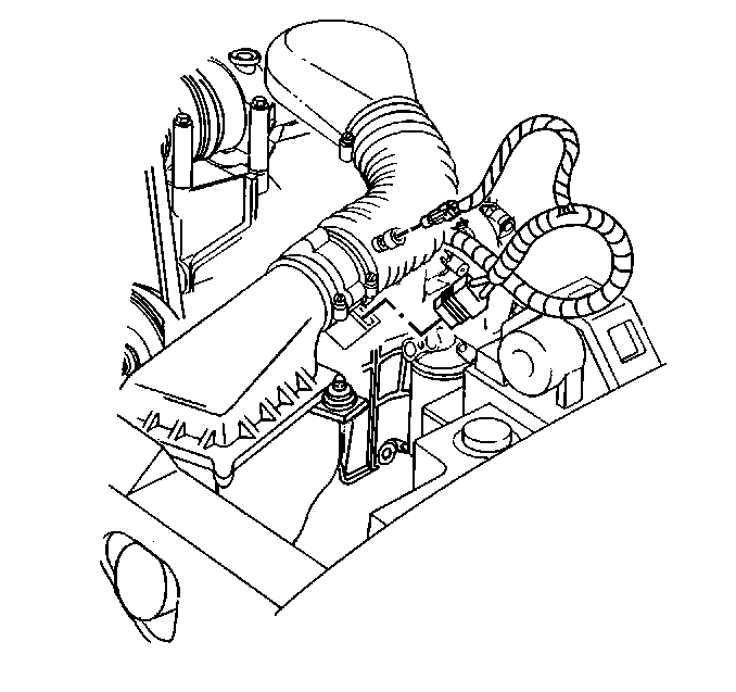
- Remove the air cleaner and air inlet duct. Refer to Air Cleaner in Engine Controls.
- Remove the following wire harnesses:
- Remove the throttle linkage. Refer to Throttle Linkage in Engine Controls.
- Remove the ignition coil. Refer to Ignition Coil in Engine Electrical.
- Remove the PCV pipe.
- Remove the vacuum hoses.
- Remove the upper intake manifold.
| • | The throttle position sensor (TP sensor) |
| • | The idle air control (IAC) motor |
| • | The manifold absolute pressure (MAP) sensor |
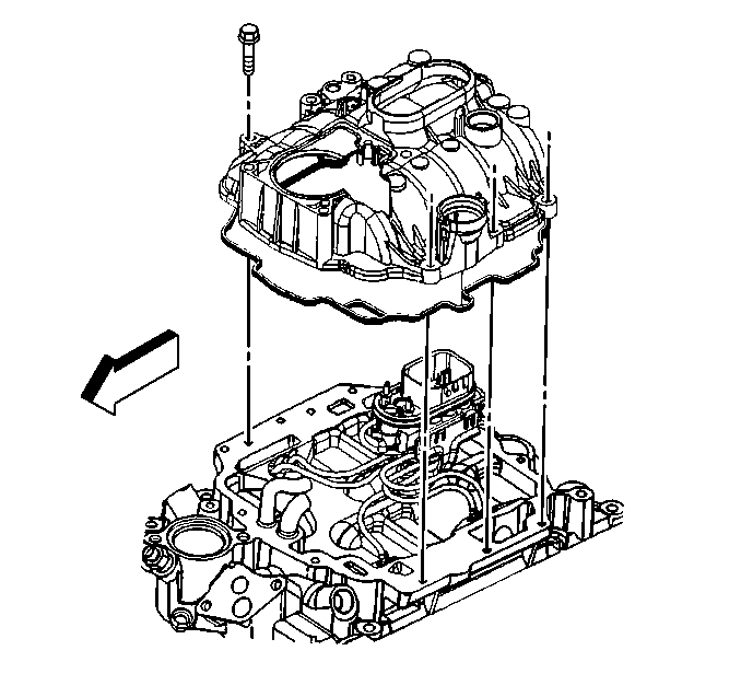
Installation Procedure
- Install the upper intake manifold. Refer to Intake Manifold Installation (Upper Intake) .
- Install the PCV pipe.
- Install the vacuum hoses.
- Install the throttle linkage. Refer to Throttle Linkage in Engine Controls.
- Install the ignition coil. Refer to Ignition Coil in Engine Electrical.
- Install the following wiring harnesses:
- Install the air cleaner and the air inlet duct. Refer to Air Cleaner in Engine Controls.
- Fill the cooling system. Refer to Draining and Filling Cooling System in Engine Cooling.

| • | The throttle position sensor (TP sensor) |
| • | The idle air control (IAC) motor |
| • | The manifold absolute pressure (MAP) sensor |
Intake Manifold Replacement Lower
Removal Procedure
- Disconnect the negative battery cable. Refer to
Caution: Unless directed otherwise, the ignition and start switch must be in the OFF or LOCK position, and all electrical loads must be OFF before servicing any electrical component. Disconnect the negative battery cable to prevent an electrical spark should a tool or equipment come in contact with an exposed electrical terminal. Failure to follow these precautions may result in personal injury and/or damage to the vehicle or its components.
. - Drain the cooling system. Refer to Cooling System Draining and Filling .
- Remove the air cleaner intake duct.
- Remove the distributor.
- Remove the upper radiator hose at the thermostat housing. Refer to Radiator Hose Replacement and Engine Coolant Thermostat Replacement .
- Remove the throttle linkage and bracket from the upper intake manifold.
- Remove the heater hoses at the lower intake manifold.
- Remove the transmission oil level indicator and tube, automatic transmissions only.
- Remove the exhaust gas recirculation (EGR) tube, clamp, and bolt. Refer to Intake Manifold Removal .
- Remove the fuel supply and return lines at the rear of the lower intake manifold.
- Remove the bolts attaching the air conditioning compressor.
- Remove the wire harnesses. Include the following items:
- Remove the positive crankcase ventilation (PCV) valve and vacuum hose.
- Remove the EGR valve inlet tube from the intake manifold.
- Remove the oxygen sensor wire support bracket and nut.
- Remove the canister purge system tubing.
- Remove the lower intake manifold. Refer to Intake Manifold Removal .
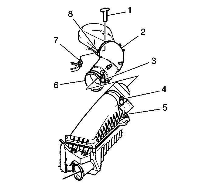
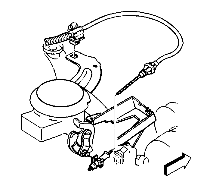
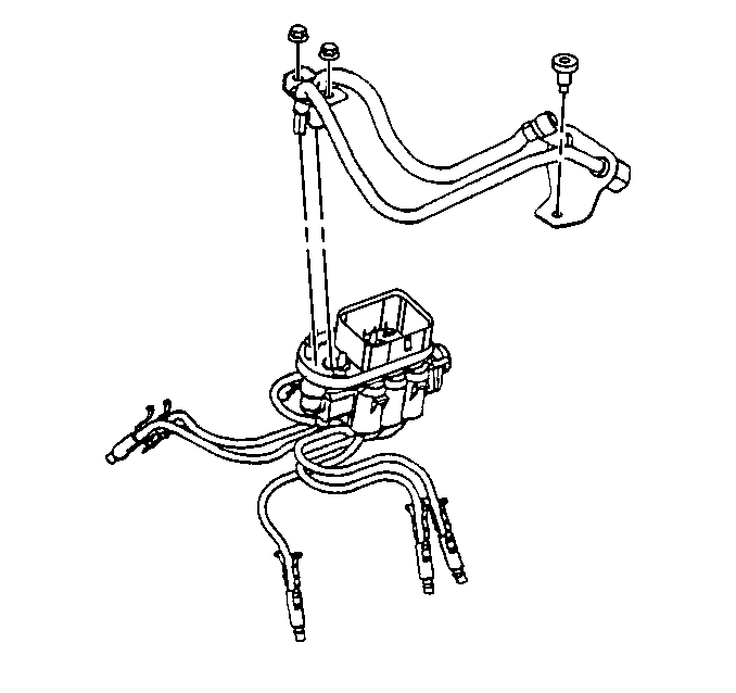
| • | The central (sequential fuel injector) |
| • | The EGR valve |
| • | The engine coolant temperature sensor |
| • | The manifold absolute pressure (MAP) sensor |
| • | The mass air flow sensor |
| • | Distributor spark plug wires |
Installation Procedure
- Install the lower intake manifold. Refer to Intake Manifold Installation .
- Install the oxygen sensor wire support bracket and nut.
- Install the EGR inlet tube, clamp, and bolt.
- Install the wiring harnesses. Include the following items:
- Install the air conditioning compressor bolts into the A/C bracket.
- Install the fuel supply and return lines to the rear of the lower intake manifold.
- Install the transmission oil level indicator and tube, automatic transmissions only.
- Install the throttle linkage and bracket from the upper intake manifold.
- Install the heater hoses at the lower intake manifold.
- Install the upper radiator hose to the thermostat housing. Refer to Radiator Hose Replacement .
- Install the distributor.
- Install the air cleaner intake duct.
- Refill the cooling system. Refer to Cooling System Draining and Filling .
- Connect the negative battery cable.
| • | The EGR valve |
| • | The engine coolant temperature sensor |
| • | The central (sequential fuel injector) |
| • | The MAP sensor |
| • | The mass air flow sensor |
| • | Distributor spark plug wires |


