Double Cardan Universal Joints Replacement Flange Yoke Replacement
Removal Procedure
Tools Required
| • | J 9522-5 U-Joint
Bearing Spacer Remover (use with J 9522-3) |
Notice: Never clamp propeller shaft tubing in a vise. Clamping propeller shaft
tubing in a vise could dent or deform the tube causing an imbalance
or unsafe condition. Always clamp on one of the yokes and support the shaft
horizontally. Avoid damaging the slip yoke sealing surface. Nicks may damage
the bushing or cut the lip seal.
Notice: The flange yoke can be replaced without removing bearing cups from the
tube yoke or ball support yoke.
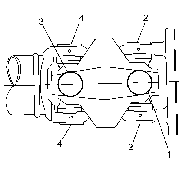
- Remove the bearing cups
in the order indicated (1-4). This is the shortest route to the heart
of the centering ball system. Make a close inspection in order to select
the correct service method.
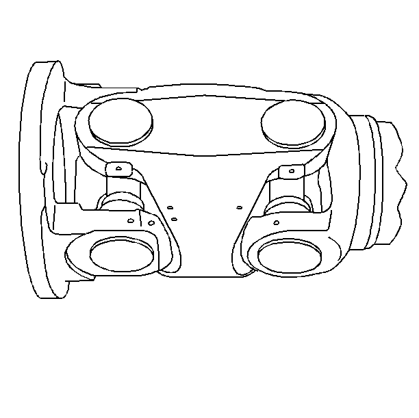
- Mark all the yokes before
disassembly in order to reassemble the yokes, and in order to retain the
driveshaft balance.
Important: You can not reassemble production universal joints. There are no bearing
retainer grooves in production bearing cups. Discard all universal joint parts
you remove.
- Support the propeller shaft in a line horizontal with the table of a
press.
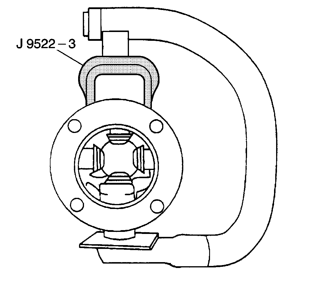
- Place the universal joint
so that the lower ear of the yoke is supported on a 30 mm (1 1/8 in)
socket.
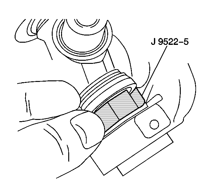
- In order to shear the plastic retaining ring on the bearing cup, place
the J 9522-5
on the open
horizontal bearing cups, and press the lower bearing cup out of the
yoke ear.
- If you have not completely removed the bearing cup, lift the cross
and insert tool J 9522-5
between the seal and the bearing cup being removed and continue pressing
the bearing cup out of the yoke.
- Rotate the propeller shaft and press the opposite bearing cup
out of the yoke.
- Inspect the retaining ring grooves for plastic.
- Inspect each bearing cup bore for burrs or imperfections.
- Clean the remains of the sheared plastic bearing retainers from
the grooves in the yoke.
- The sheared plastic may prevent the bearing cups from being pressed
into place. This prevents the bearing retainers from being properly seated.
Installation Procedure

- Assemble the flange yoke
on the inner cross of the ball tube yoke.
- Assemble the bearing cup assemblies.
- Assemble the ball support yoke cross in the flange yoke. Orient
the ball support yoke cross with the tube yoke according to the marks made
on disassembly.
- Inspect all the trunnions for freedom of rotation.
- If the trunnions are too tight, strike the flange yoke sharply
with a hammer in order to aid in seating the retaining rings.
Double Cardan Universal Joints Replacement Centering Ball Replacement
Tools Required
| • | J 23694 C.V.
Propeller Shaft Seal Installer |
Important: Production universal joints may not be reassembled. The production bearing
cups do not have bearing retainer grooves. Discard all universal joint parts
that are removed.
- Disassemble the flange yoke assembly.
- Inspect the ball seat insert bushing for wear.
- If the bushing is worn, replace the ball support yoke and cross
assembly.
- Inspect the seal and ball seats along with the spring and washers.
If any parts show indication of excessive wear or are broken, replace
the entire set with a service kit. Always discard the removed seal and replace
the seal.
- Inspect the centering ball surface.
- If the ball surface shows signs of wear beyond a smooth polish,
replace the ball.
- Clean all of the plastic from the grooves of all the yokes. Drive
a small pin or punch through the injection holes in order to remove the plastic.
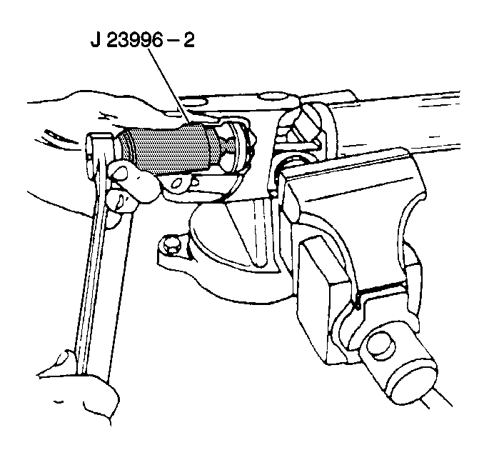
Notice: When a centering ball requires replacement, all ball seat components
must be replaced also. A separate ball and seat service kit is available.
The kit has two seat springs and the longer spring must be discarded.
- Disassemble the shaft in a bench vise.
- Install the ball puller, J 23996-2
over the ball.
- Tighten the puller nut finger tight.
- Apply a light coat of multipurpose grease to the jaws of the ball
puller tool in order to reduce friction between the jaws and the inside surface
of the tool sleeve.
- Tighten the nut until the ball is removed from the stud.
- Position a new ball on the stud.
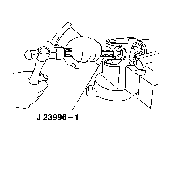
- Position the J 23996-1
against the ball and drive the tool
with a hammer until the ball bottoms on the stud.
- Replace the ball seats and components. Refer to
Double Cardan Universal Joints Replacement
.
Double Cardan Universal Joints Replacement Ball Seat Assembly
Tools Required
J 23694 Seal Installer
- Remove the centering ball. Refer to
Double Cardan Universal Joints Replacement
.
Important: Take care not to damage the seal bore when prying the seal.
- Pry the grease seal from the ball seat housing.
- Remove the large washer, the three seats, the small washer and
the spring from the seat housing.
- Wash the bore of the housing thoroughly with mineral spirits in
order to remove all traces of old lubricant.
- Dry the bore of the housing thoroughly with compressed air.
- Obtain a ball and seat kit. Discard the longer of the two springs
in the kit.
- Liberally grease the inside diameter of the ball seat housing.
Use the grease supplied in the kit.
- Thoroughly grease and install the following parts in the ball
seat housing:
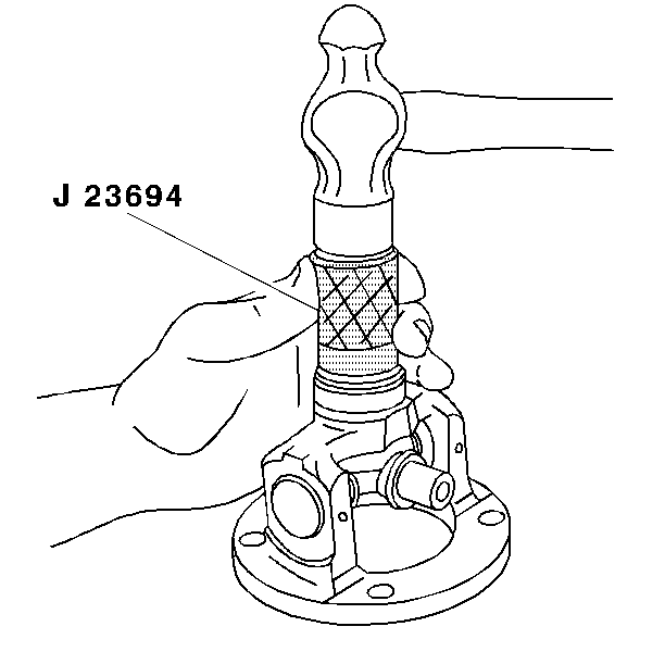
- Install the grease seal.
| 9.1. | Position the grease seal on the housing with the seal lip facing
down into bore. |
| 9.2. | Place the J 23694
over the seal and tap the seal into place. The seal is seated when
flush with the housing. |
- Pack the remaining grease from the ball and seat kit in the seat
assembly and on the seal. Make sure the inner surfaces of the seats are liberally
lubricated.
- Position the ball support yoke and cross assembly in the flange
yoke. Align the reference marks made at disassembly.
- Install the bearing cups.
- Check the ball seat assembly. The ball support yoke snaps over
the center and moves to the right or left and up or down freely if the constant
velocity joint is correctly assembled.


