GM Service Manual Online
For 1990-2009 cars only

Removal Procedure

  1. Disconnect the battery negative cable. Refer to Battery Negative Cable Disconnection and Connection in Engine Electrical.
  2. Remove the engine cover. Refer to Engine Cover Replacement in Interior Trim.
  3. Drain the cooling system. Refer to Cooling System Draining and Filling in Engine Cooling.
  4. Remove the air cleaner assembly. Refer to Air Cleaner Assembly Replacement in Engine Controls-4.3L.
  5. Remove the air cleaner outlet duct from the throttle body assembly. Refer to Air Cleaner Outlet Resonator Replacement in Engine Controls-4.3L.
  6. Disconnect the accelerator control cable from the throttle shaft and the accelerator control cable bracket. Refer to Accelerator Control Cable Replacement in Engine Controls-4.3L.
  7. Perform this step if the vehicle is equipped with a cruise control. Disconnect the cruise control cable from the throttle shaft, and from the accelerator control cable bracket. Refer to Cruise Control Cable Replacement in Cruise Control.

  8. Object Number: 172995  Size: SH
  9. Disconnect PCV valve hose assembly from the intake manifold and the valve rocker arm cover.

  10. Object Number: 363391  Size: SH
  11. Remove the nut holding the A/C hose bracket to the intake manifold stud, if equipped.
  12. Remove the nut holding the engine wiring harness bracket to the intake manifold stud.

  13. Object Number: 527368  Size: SH
  14. Disconnect the following electrical connectors:
  15. • The A/C compressor clutch, if equipped (1)
    • The A/C high pressure cutoff switch, if equipped (5)
    • The throttle position (TP) sensor (2)
    • The idle air control (IAC) motor (3)
    • The fuel meter body assembly connector (4)

    Object Number: 527362  Size: SH
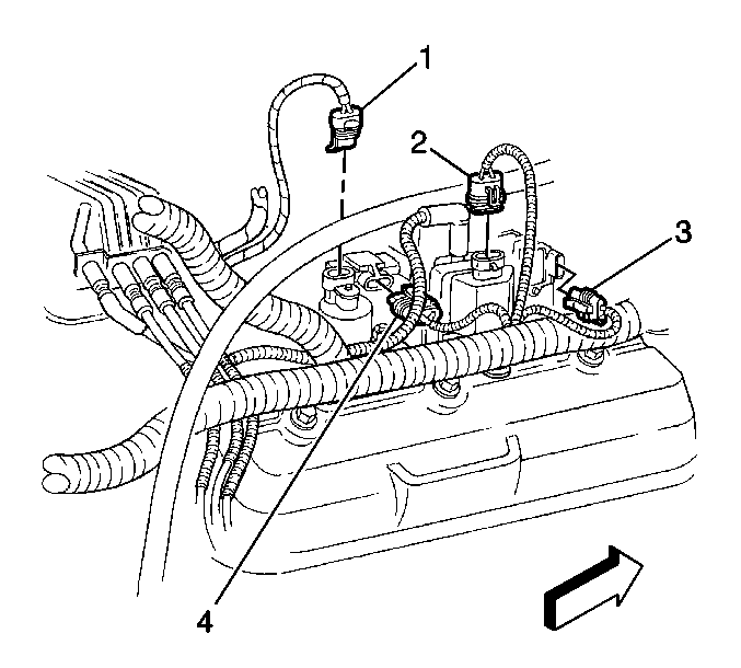
  16. Disconnect the following electrical connectors:
  17. • The manifold absolute pressure (MAP) sensor (4)
    • The EVAP canister purge solenoid valve (1)

    Object Number: 527361  Size: SH
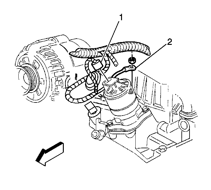
  18. Disconnect the EGR valve electrical connector (1).
  19. Remove the ground wire (2) from the stud at the water outlet.

  20. Object Number: 363396  Size: SH
  21. Remove the nut, and remove the engine wiring harness bracket from the stud, at the EVAP canister purge solenoid valve.
  22. Move and secure the engine wire harness out of the way.
  23. Remove the EVAP canister purge valve. Refer to Evaporative Emission Canister Purge Solenoid Valve Replacement in Engine Controls-4.3L.

  24. Object Number: 71614  Size: SH
  25. Remove the radiator inlet hose at the water outlet. Refer to Radiator Hose Replacement in Engine Cooling.
  26. Remove the heater hose from the intake manifold. Refer to Heater Water Bypass Valve Replacement in Heating Ventilation and Air Conditioning.
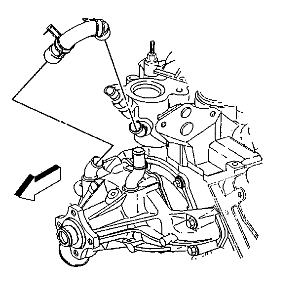
  27. Remove the water pump inlet hose from the intake manifold.

  28. Object Number: 528458  Size: SH
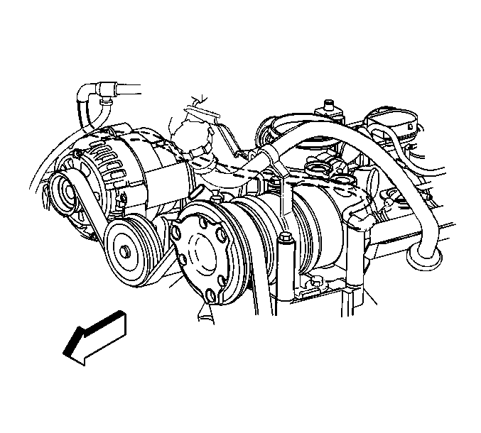
  29. Disconnect the vacuum hose from the intake manifold.

  30. Object Number: 527356  Size: SH
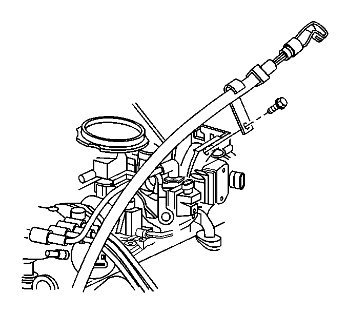
  31. Remove the bolt holding the transmission fluid filler tube to the accelerator control cable bracket.

  32. Object Number: 398027  Size: SH
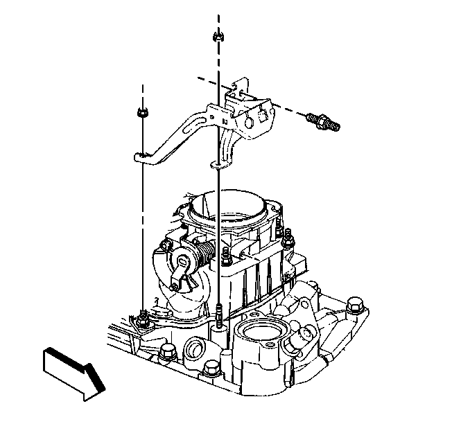
  33. Remove the accelerator control cable bracket from the throttle body and the intake manifold.
  34. Remove the distributor. Refer to Distributor Replacement in Engine Controls-4.3L.
  35. Disconnect the fuel supply, and disconnect the return pipes, at the rear of the intake manifold. Refer to Fuel Hose/Pipes Replacement - Engine Compartment in Engine Controls-4.3L.
  36. Remove the ignition control module (ICM). Refer to Ignition Control Module Replacement in Engine Controls-4.3L.
  37. Remove the exhaust gas recirculation (EGR) valve inlet pipe from the intake, and from the exhaust manifolds. Refer to Exhaust Gas Recirculation Pipe Replacement in Engine Controls-4.3L.

  38. Object Number: 340090  Size: SH
  39. In order to remove the front intake manifold bolt, perform the following steps:
  40. 28.1. Remove the drive belt. Refer to Drive Belt Replacement .
    28.2. Remove the A/C compressor side brace.
    28.3. Loosen the nut for the power steering pump rear bracket.
    28.4. Remove the oil filler tube bracket bolt and the oil filler tube.
    28.5. Remove the bolts and the nut for the power steering pump mounting bracket.
    28.6. Leave the A/C compressor, if equipped, and the power steering pump on the bracket.
    28.7. Slide the power steering pump bracket forward to access the bolt at the front of the intake manifold.
  41. Remove the lower intake manifold. Refer to Lower Intake Manifold Replacement in Engine Mechanical.
  42. Clean all sealing surfaces and the intake manifold. Refer to Intake Manifold Cleaning and Inspection in Engine Mechanical.
  43. If the intake manifold requires replacement, refer to Intake Manifold Disassemble , and to Intake Manifold Assemble .

Installation Procedure

  1. Install the lower intake manifold. Refer to Lower Intake Manifold Replacement .
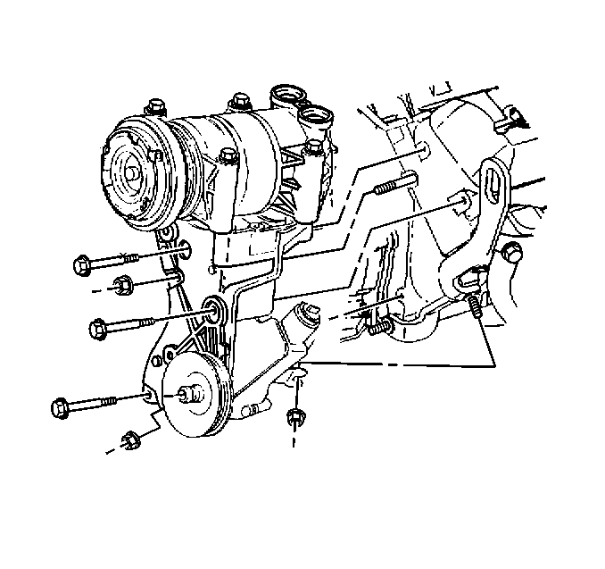
  2. Object Number: 340090  Size: SH
  3. Reposition the power steering pump mounting bracket.
  4. Notice: Use the correct fastener in the correct location. Replacement fasteners must be the correct part number for that application. Fasteners requiring replacement or fasteners requiring the use of thread locking compound or sealant are identified in the service procedure. Do not use paints, lubricants, or corrosion inhibitors on fasteners or fastener joint surfaces unless specified. These coatings affect fastener torque and joint clamping force and may damage the fastener. Use the correct tightening sequence and specifications when installing fasteners in order to avoid damage to parts and systems.

  5. Install the power steering pump mounting bracket three bolts and the nut.
  6. Tighten
    Tighten the power steering pump mounting bracket bolts and the nut and the power steering pump rear bracket nut to 41 N·m (30 lb ft).

  7. Install A/C compressor side brace and bolts.
  8. Tighten

    1. Tighten the A/C compressor side brace bolt to 50 N·m (37 lb ft).
    2. Tighten the side brace bolt to the generator bracket to 25 N·m (18 lb ft).
  9. Install the oil filler tube and bolt.
  10. Tighten
    Tighten the oil filler tube bolt to 25 N·m (18 lb ft).

  11. Install the drive belt. Refer to Drive Belt Replacement .
  12. Install the exhaust gas recirculation (EGR) valve inlet pipe to the intake and the exhaust manifolds. Refer to Exhaust Gas Recirculation Pipe Replacement in Engine Controls-4.3L.
  13. Install the EVAP canister purge valve. Refer to Evaporative Emission Canister Purge Solenoid Valve Replacement in Engine Controls-4.3L.
  14. Install the fuel supply and return pipes to the rear of the intake manifold. Refer to Fuel Hose/Pipes Replacement - Engine Compartment in Engine Controls-4.3L.
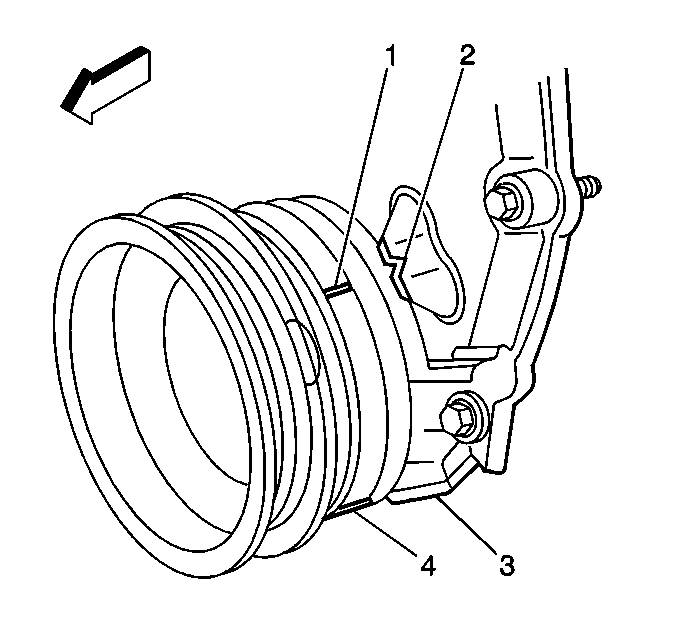
  15. Object Number: 334551  Size: SH

    Important: In order to install the distributor for the correct engine timing, position the engine to number one cylinder top dead center.

  16. Remove the spark plug for number one cylinder.
  17. Rotate the crankshaft until number one cylinder is in the compression stroke.
  18. Align the 2 reference marks on the crankshaft balancer (1,4)) with the 2 alignment marks (2,3) on the front cover.
  19. Install the spark plug. Refer to Spark Plug Replacement in Engine Controls-4.3L.
  20. Install the distributor. Refer to Distributor Replacement in Engine Controls-4.3L.
  21. Install the ICM. Refer to Ignition Control Module Replacement in Engine Controls-4.3L.
  22. Object Number: 398027  Size: SH
  23. Install the accelerator control cable bracket, studs, and nuts to the intake manifold and the throttle body.
  24. Tighten
    Tighten the accelerator control cable bracket nuts and studs to 12 N·m (106 lb in).

    Object Number: 528458  Size: SH
  25. Install the vacuum hose to the intake manifold.
  26. Object Number: 527356  Size: SH
  27. Install the transmission fluid fill tube and bolt to the accelerator control cable bracket.
  28. Tighten
    Tighten the transmission fluid fill tube bolt 6 N·m (53 lb in).

    Object Number: 71614  Size: SH
  29. Install the water pump inlet hose to the intake manifold.
  30. Install the heater hoses. Refer to Heater Water Bypass Valve Replacement in Heating Ventilation and Air Conditioning.
  31. Install the radiator inlet hose to the water outlet. Refer to Radiator Hose Replacement in Engine Cooling.
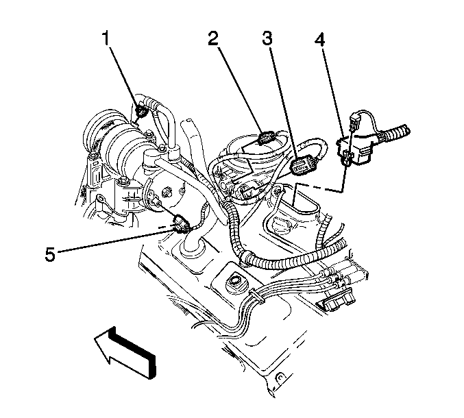
  32. Object Number: 527368  Size: SH
  33. Position the engine wiring harness.
  34. Connect the following electrical connectors:
  35. • The A/C compressor clutch, if equipped (1)
    • The A/C high pressure cutoff switch, if equipped (5)
    • The throttle position (TP) sensor (2)
    • The idle air control (IAC) motor (3)
    • The fuel meter body assembly connector (4)

    Object Number: 527362  Size: SH
  36. Connect the following electrical connectors:
  37. • The manifold absolute pressure (MAP) sensor (4)
    • The EVAP canister purge solenoid valve (1)

    Object Number: 527361  Size: SH
  38. Connect the EGR valve electrical connector (1).
  39. Install the ground wire (2) and the nut to the water outlet stud.
  40. Tighten
    Tighten the ground wire nut to 19 N·m (14 lb ft).
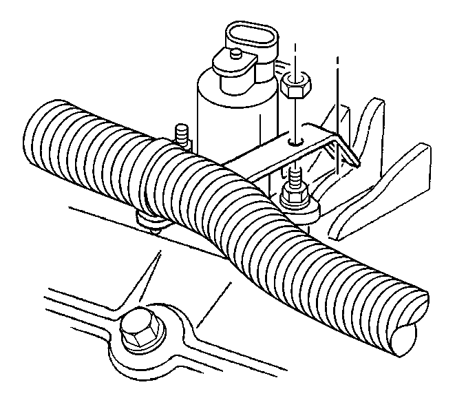

    Object Number: 363396  Size: SH
  41. Install the nut and the engine wiring harness bracket to the stud for the EVAP canister purge valve.
  42. Tighten
    Tighten the engine wiring harness bracket nut to 8 N·m (71 lb in).
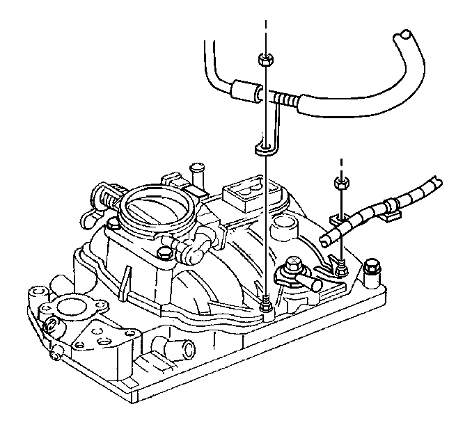

    Object Number: 363391  Size: SH
  43. Install the nut and the engine wiring harness bracket to the intake manifold stud.
  44. Tighten
    Tighten the engine wiring harness bracket nut to 12 N·m (106 lb in).

  45. Install the nut and the A/C hose bracket to the intake manifold stud, if equipped.
  46. Tighten
    Tighten the A/C hose bracket nut to 5 N·m (44 lb in).
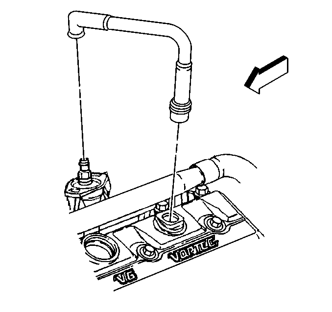

    Object Number: 172995  Size: SH
  47. Install the PCV valve hose assembly to the intake manifold and the valve rocker arm cover.
  48. Install the cruise control cable, if equipped to the throttle shaft and the accelerator control cable bracket. Refer to Cruise Control Cable Replacement in Cruise Control.
  49. Install the accelerator control cable to the throttle shaft and the accelerator control cable bracket. Refer to Accelerator Control Cable Replacement in Engine Controls-4.3L.
  50. Refill the cooling system. Refer to Cooling System Draining and Filling in Engine Cooling.
  51. Install air cleaner outlet duct to the throttle body. Refer to Air Cleaner Outlet Resonator Replacement in Engine Controls-4.3L.
  52. Install the air cleaner assembly. Refer to Air Cleaner Assembly Replacement in Engine Controls-4.3L.
  53. Connect the battery negative cable. Refer to Battery Replacement in Engine Electrical.
  54. Install the engine cover. Refer to Engine Cover Replacement in Interior Trim.