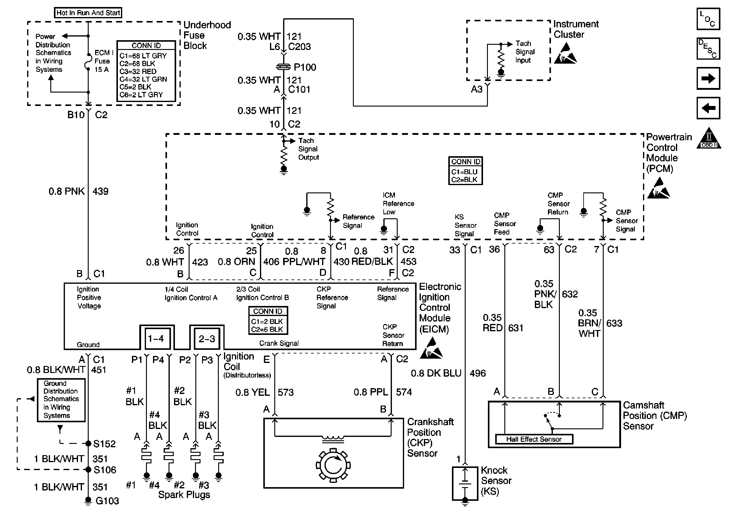
Refer to
Ignition Controls

.
Circuit Description
This engine is equipped with a distributorless ignition system called the electronic ignition (EI) system. The primary circuit of the EI system consists of 2 separate ignition coils, an electronic ignition control module (ICM) and a crankshaft position (CKP) sensor as well as the related connecting wires and the ignition control (IC) portion of the powertrain control module (PCM). Each secondary circuit consists of the secondary winding of the coil, spark plug wires and the spark plugs.
Important: The camshaft position (CMP) sensor is only used for a misfire detection and is not part of the ignition system.
Diagnostic Aids
| • | A small amount of resistance in the battery positive voltage circuit to the PCM may cause a no start. Test the battery positive voltage circuit for excessive resistance or corrosion. Refer to Wiring Repairs in Wiring Systems. |
| • | The PCM grounds will cause a NO START only if all of them are not making a good connection. Refer to Testing for Intermittent Conditions and Poor Connections in Wiring Systems. |
| • | Test/inspect the throttle position (TP) sensor for the following conditions: |
| - | Binding |
| - | Sticking |
| - | Intermittently shorted |
| - | Intermittently open |
| • | The ECT may be skewed within specifications and not set a code. On a cold vehicle the ECT and IAT should be 3° C or 5° F of each other. On a HOT vehicle let cool to ambient temperature then test. |
| • | The MAP sensor may be skewed within specifications and not set a code. Refer to DTC P0105 Manifold Absolute Pressure (MAP) Sensor Performance/Range for diagnostic testing. |
| • | If the CKP sensor is loose it may cause an intermitted NO START by moving away from the reluctor wheel. Inspect the sensor and matting surface for being clean and tight. |
Test Description
The numbers below refer to the step numbers on the diagnostic table.
-
If the engine starts, the problem could be intermittent. Basic engine mechanical problems, the vehicle theft deterrent (VTD) system (if equipped) and poor connections could cause a no start condition.
-
This step will determine if the cause of the no start or start and stall is related to the VTD.
-
If the signal is over 2.5 volts, the engine may be in the Clear Flood Mode which will cause starting problems.
-
If the engine coolant sensor is below -30°C (-22°F), the PCM provides fuel for this extremely cold temperature which will severely flood the engine.
-
Voltage at the spark plug is checked using the spark plug tester tool. No spark indicates a basic ignition problem.
-
This test will determine if there is fuel pressure at the fuel injection unit and holding steady.
-
Use the injector test lamp in order to test the injector circuits. A blinking lamp indicates that the PCM is controlling the injector.
Step | Action | Values | Yes | No |
|---|---|---|---|---|
1 | Did you perform the Powertrain On-Board Diagnostic (OBD) System Check? | -- | ||
Attempt to start the engine. Does the engine start and continue to Run? | -- | Go to Symptoms | ||
Does the VTD Password Learn Mode parameter display active while you crank the engine? | -- | Go to Diagnostic System Check - Theft Deterrent in Theft Deterrent | ||
4 | Monitor the engine RPM parameter while cranking the engine. Does the engine RPM increment while the engine is cranking? | -- | Go to DTC P0336 Crankshaft Position (CKP) Sensor Performance | |
Monitor the TP sensor on the scan tool. Is the TP sensor more than the specified value with the throttle closed? | 2.5 V | Go to DTC P0105 Manifold Absolute Pressure (MAP) Sensor Performance/Range | ||
Monitor the ECT sensor on the scan tool. Is the ECT sensor below the specified value? | -30°C (-22°F) | Go to DTC P0118 Engine Coolant Temperature (ECT) Sensor Circuit High Voltage | ||
7 | Inspect the ECM B fuse and the ECM 1 fuse for an open. Did you find a condition? | -- | ||
Check for spark at two spark plug wires using the J 26792 spark tester. Is spark present at both spark plug wires? | -- | |||
Is the fuel pressure within the specified range? | 380-410 kPa (55-60 psi | Go to Fuel System Diagnosis | ||
10 |
Does the test lamp illuminate? | -- | ||
Does the test lamp flash for each injector circuit? | -- | Go to Diagnostic Aids | Go to Fuel Injector Circuit Diagnosis | |
12 | Repair the circuit as necessary. Refer to Wiring Repairs in Wiring Systems. Does the engine start and Run? | -- | System OK | Go to Diagnostic Aids |
