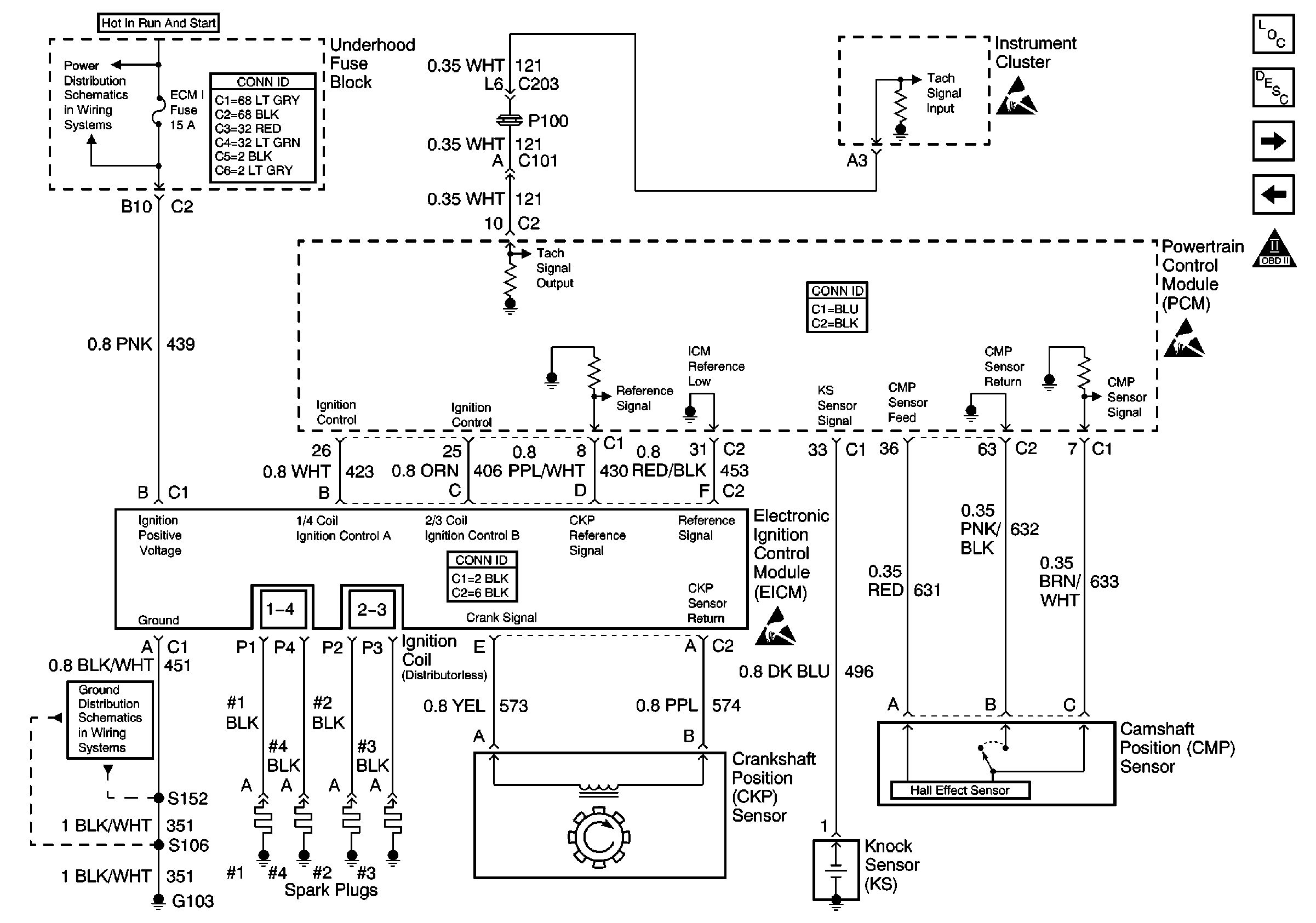
Refer to
Ignition Controls

.
Circuit Description
The electronic ignition control module (ICM) sends a reference signal to the powertrain control module (PCM) seven times per crankshaft revolution (7X reference) in order to indicate the crankshaft position and the RPM so that the PCM can determine when to pulse the ignition coils and control the ignition timing. The ICM applies 5 volts through the 7X reference circuit to the PCM. The PCM switches this circuit to ground for a very short period of time. The seventh pulse is the sync pulse and is used for crankshaft position reference.
Conditions For Running The DTC
| • | The engine is running. |
| • | DTC P0340 or P0341 is not set. |
Conditions for Setting the DTC
The CKP resync counter exceeds 15 within 4 minutes and 15 seconds.
Action Taken When the DTC Sets
| • | The malfunction indicator lamp (MIL) will illuminate after two consecutive ignition cycles in which the diagnostic runs with the malfunction present |
| • | The PCM records the operating conditions at the time when the diagnostic fails. This information stores in the Freeze Frame and Failure Records buffers. |
| • | A history DTC stores. |
Conditions for Clearing the MIL/DTC
| • | The MIL will turn OFF after 3 consecutive ignition cycles in which the diagnostic runs without a fault. |
| • | A history DTC will clear after 40 consecutive warm up cycles without a fault. |
| • | The DTC can be cleared by using the scan tool. |
Diagnostic Aids
| • | Inspect the CKP sensor harness in order to ensure that it is not routed too close to any non-engine related electronic component or harness. |
| • | Inspect the wiring harness for damage. If the harness appears to be OK, observe the medium resolution resync counter on the scan tool while moving connectors and wiring harnesses related to the CKP sensor. If the medium resolution resync counter still does not count, then while still observing the scan tool, operate any non-engine related electrical components on the vehicle. A change in display will indicate the location of the malfunction. |
| • | A rubbed through wire insulation or a poor connection may cause an intermittent problem. |
| • | A defective reluctor wheel or a cracked or damaged CKP sensor can result in an intermittent. Remove the crankshaft sensor and inspect for any damage. With the CKP sensor removed you can also inspect the reluctor wheel through the hole. Check the porosity and condition of the wheel. The reluctor edges must be square. Look for nicked or damaged reluctor wheel. |
Test Description
The numbers below refer to the step numbers on the diagnostic table:
Step | Action | Values | Yes | No | ||||||||
|---|---|---|---|---|---|---|---|---|---|---|---|---|
1 | Did you perform the Powertrain On-Board Diagnostic (OBD) System Check? | -- | ||||||||||
2 | Attempt to start the engine. Does the engine start and run? | -- | ||||||||||
3 | Visually inspect the wiring harness of the CKP sensor including the CKP reference signal circuit from the ICM to the PCM for improper routing near high voltage circuits, all other circuitry or for contacting any metal surface and moving components. Did you find and correct any condition? | -- | ||||||||||
With the engine running, wiggle the harness connectors of the following components and related circuits, while listening for the engine to stumble:
Does the engine stumble? | -- | Go to Diagnostic Aids | ||||||||||
5 |
Did you find and correct the condition? | -- | ||||||||||
6 |
Did you find and correct the condition? | -- | ||||||||||
7 |
Did you find and correct the condition? | -- | Go to Diagnostic Aids | |||||||||
8 |
Does the DTC reset? | -- | System OK |
