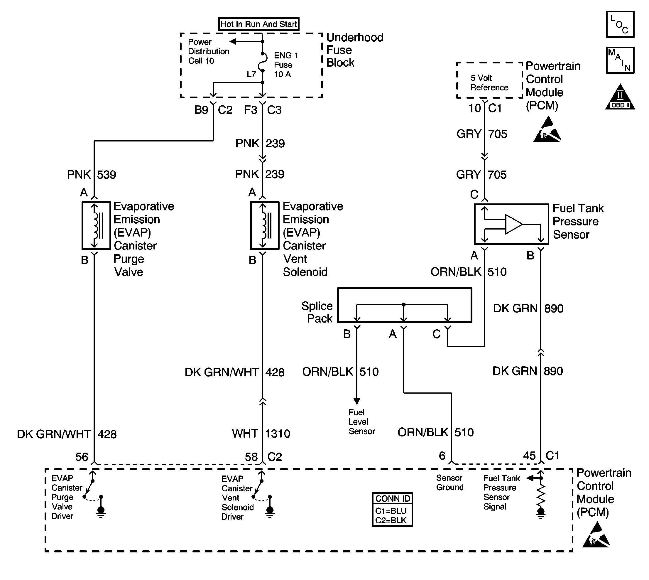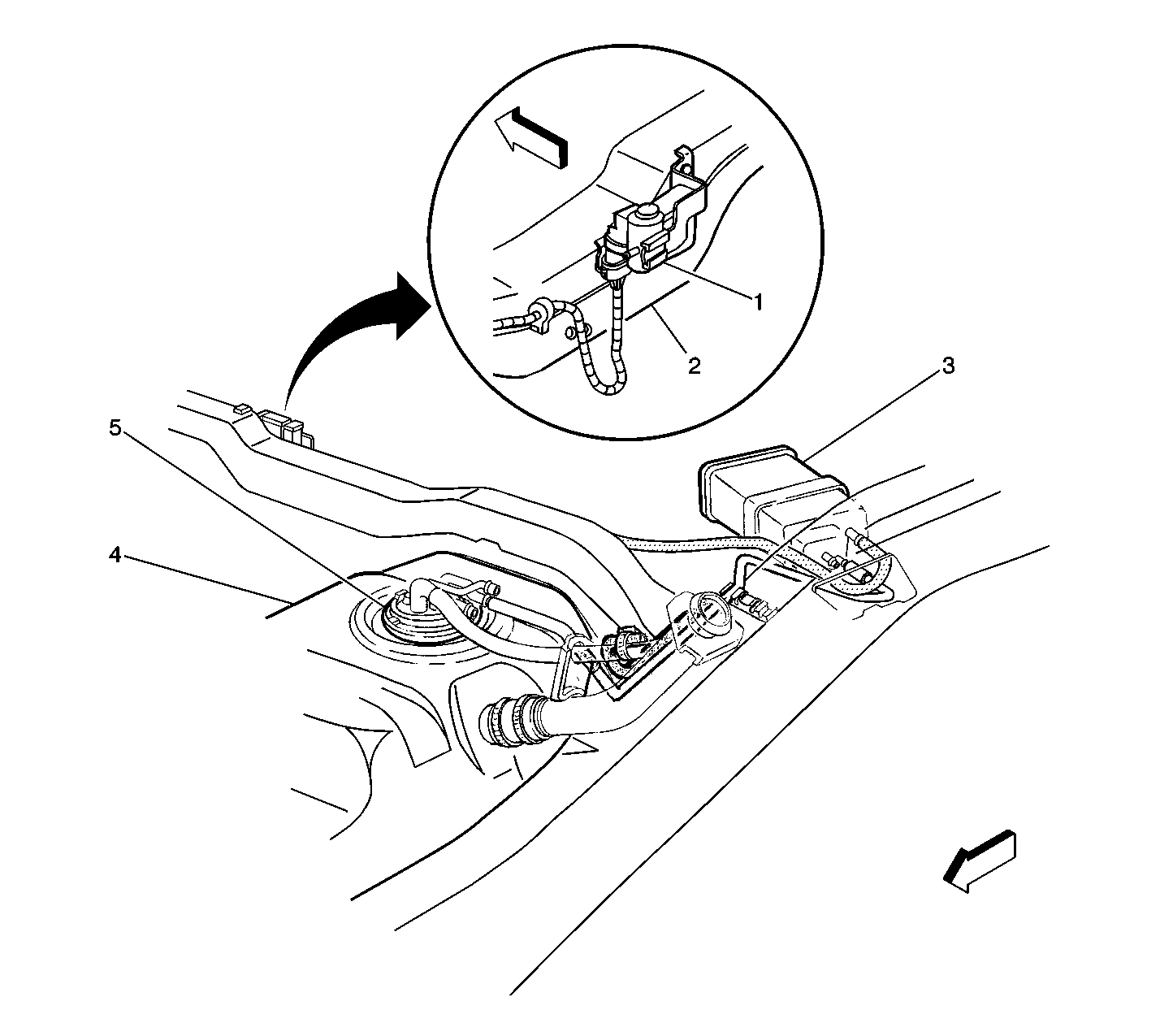
System Description
The EVAP System includes the following components:
| • | The fuel tank |
| • | The EVAP vent valve |
| • | The fuel pipes and hoses |
| • | The fuel fill cap |
| • | The EVAP vapor pipes |
| • | The EVAP purge pipes |
| • | The EVAP canister |
| • | The EVAP canister purge valve |
A RESTRICTED or BLOCKED EVAP VENT PATH is detected by monitoring fuel tank pressure during normal operation (EVAP vent valve open, EVAP canister purge valve normal). With the EVAP vent valve open, vacuum level in the system should be very low unless the vent path is blocked.
Conditions for Running the DTC
All conditions for P0440 and P0442 have been met and Passed.
Conditions for Setting the DTC
| • | Fuel tank pressure is less than -10 inches H2O. |
| • | The condition is present for up to 30 seconds. |
Action Taken When the DTC Sets
| • | The PCM will illuminate the MIL during the second consecutive trip in which the diagnostic test has been run and failed. |
| • | The PCM will store conditions which were present when the DTC set as Freeze Frame/Failure Records data. |
Conditions For Clearing the MIL/DTC
| • | The PCM will turn the MIL OFF during the first trip in which the diagnostic has been run and Passed. |
| • | The history DTC will clear when the PCM turns OFF the MIL. |
| • | The DTC can be cleared by using the scan tool. |
Diagnostic Aids
The following conditions will set DTC P0446.
| • | Faulty EVAP vent valve (stuck closed). |
| • | Plugged, kinked or pinched vent hose. |
| • | Shorted EVAP vent valve driver circuit. |
| • | Plugged EVAP canister. |
If the DTC is determined to be intermittent, reviewing the Failure Records can be useful in determining when the DTC was last set.
If the condition is intermittent refer to Intermittent Conditions .
Test Description
The numbers below refer to the step numbers on the Diagnostic Table.
-
This step verifies that a fuel tank pressure sensor circuit is not causing the condition.
-
This step verifies that the Fuel Tank Pressure sensor responds to a change in vacuum.
-
This step isolates the EVAP system from the Fuel Tank Pressure sensor. A Fuel Tank Pressure sensor that does not correctly respond to pressure (or vacuum) causes this DTC to set.
The Fuel Tank Pressure sensor range is from 7.5 in. H2O of pressure to -17.5 in. H2O of pressure (vacuum).
-
This step tests the EVAP vent valve circuits. If the EVAP vent valve clicks when commanded ON and OFF, then the PCM and wiring are OK.
Step | Action | Values | Yes | No | ||||
|---|---|---|---|---|---|---|---|---|
1 | Did you perform the Powertrain On-Board Diagnostic (OBD) System Check? | -- | ||||||
Is the fuel tank pressure sensor voltage less than the specified value? | 4V | Go to DTC P0453 Fuel Tank Pressure Sensor Circuit High Voltage | ||||||
3 |
Does the fuel tank pressure sensor voltage increase to more than the specified value? | 4.5V | ||||||
Does the fuel tank pressure voltage change when the EVAP canister purge valve is enabled? | -- | Go to Diagnostic Aids | ||||||
Does the fuel tank pressure change as vacuum is applied? | 10 in Hg | |||||||
6 |
Did you find and correct the condition? | -- | ||||||
Command the EVAP vent valve ON and OFF with a scan tool. Refer to
Do you hear an audible click as the EVAP vent valve is commanded ON and OFF. | -- | |||||||
8 |
Does the vacuum drop from the specified value when the EVAP Vent Valve is opened? | 5 in. Hg. | ||||||
9 | Remove the plug from the vent line while monitoring the hand held vacuum pump gauge. Does the vacuum drop from the specified value when the vent line is unplugged? | 5 in. Hg. | ||||||
10 |
Is the test lamp illuminated? | -- | ||||||
11 | Test the control circuit of the EVAP vent valve for a short to ground. Refer to Circuit Testing and Wiring Repairs in Wiring Systems. Did you find and correct the condition? | -- | ||||||
12 |
Did you find and correct the condition? | -- | ||||||
13 | Repair the restriction between the fuel tank pressure sensor and the EVAP canister. Did you complete the repair? | -- | -- | |||||
14 | Replace the EVAP Vent Valve. Refer to Evaporative Emission Vent Valve Replacement . Did you complete the replacement? | -- | -- | |||||
15 | Replace the EVAP Canister. Refer to Evaporative Emission Canister Replacement . Did you complete the replacement? | -- | -- | |||||
16 | Replace the Fuel Tank Pressure sensor. Refer to Fuel Tank Pressure Sensor Replacement . Did you complete the replacement? | -- | -- | |||||
17 | Replace the PCM. Refer to Powertrain Control Module Replacement/Programming . Did you complete the replacement? | -- | -- | |||||
18 |
Does the DTC reset? | -- | ||||||
19 | Select the Capture Info option and the Review Info option using the scan tool. Does the scan tool display any DTCs that you have not diagnosed? | -- | Go to the applicable DTC | System OK |

