Transmission Housing Oil Seal Replacement Rear
Tools Required
| • | J 23129 Universal Seal Remover |
| • | J 6125-1B Slide Hammer |
| • | J 36503 Seal Installer |
Removal Procedure
- Raise and support the vehicle. Refer to Lifting and Jacking the Vehicle in General Information.
- Remove the rear propeller shaft. Refer to One-Piece Propeller Shaft Replacement or Two-Piece Propeller Shaft Replacement in Propeller Shaft.
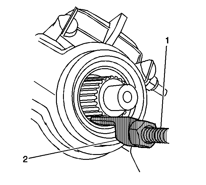
- Remove the rear oil seal from the rear case using the J 6125-1B (1) and the J 23129 (2).
- Remove the rear oil seal from the extension housing.
Installation Procedure
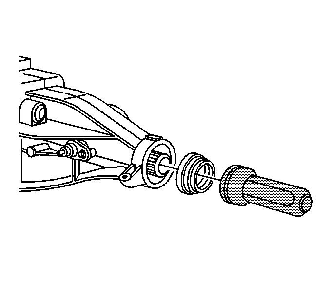
- Using the J 36503 install the new rear oil seal.
- Install the rear propeller shaft. Refer to One-Piece Propeller Shaft Replacement or Two-Piece Propeller Shaft Replacement in Propeller Shaft.
- Fill the transmission to the proper fluid level. Refer to Transmission Fluid Replacement .
- Lower the vehicle.
Transmission Housing Oil Seal Replacement Front
Tools Required
| • | J 41371 Reluctor Gear Puller |
| • | J 38801 Input Shaft Seal Installer |
Removal Procedure
- Raise and support the vehicle. Refer to Lifting and Jacking the Vehicle in General Information.
- Remove the rear propeller shaft. Refer to One-Piece Propeller Shaft Replacement or Two-Piece Propeller Shaft Replacement in Propeller Shaft.
- Remove the transmission. Refer to Transmission Replacement .
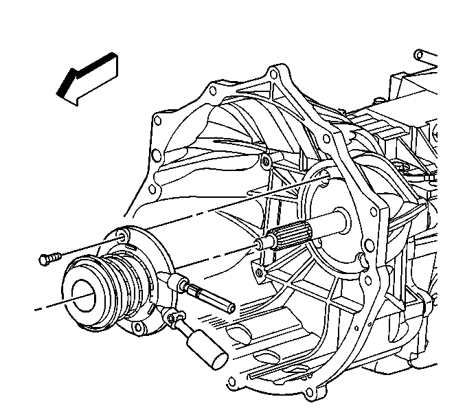
- Remove the clutch actuator bolts.
- Remove the clutch actuator from the input shaft.
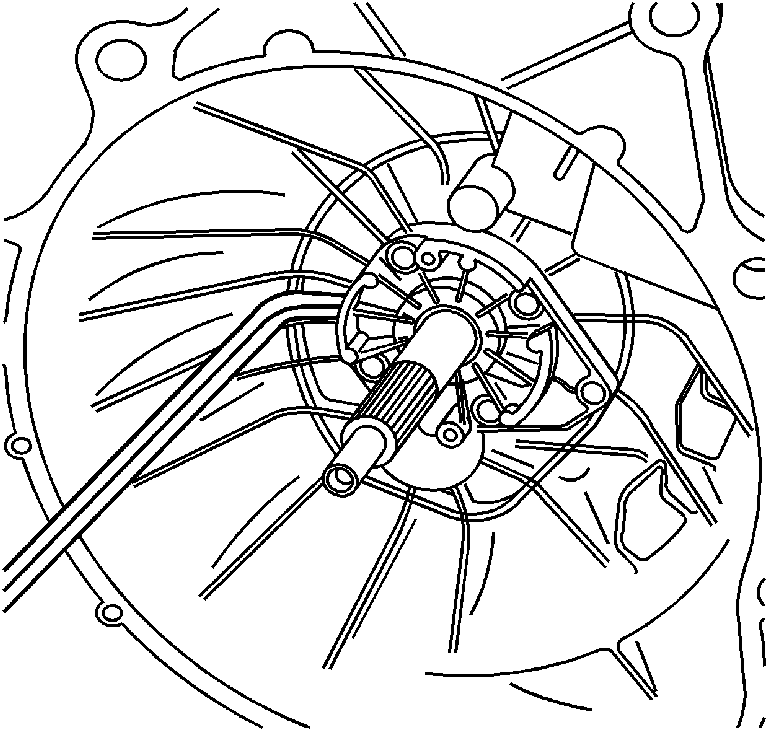
- Remove the 5 bolts from the front bearing retainer.
- Use suitable prying tool to remove the input shaft bearing retainer.
- Remove the input shaft retaining ring.
- Remove the Input shaft seal from the input shaft bearing retainer.
- Remove the old gasket material from the front bearing retainer.
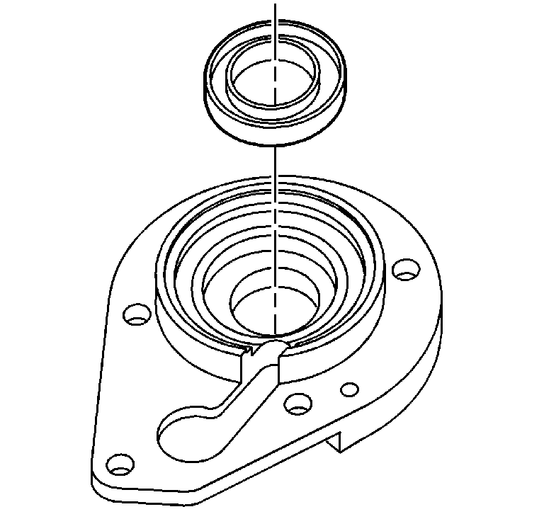
Installation Procedure
Important: Inspect the bearing retainer for any nicks or cracks that may result in a leak. Replace if necessary.
- Install the retaining ring on the input shaft bearing.
- Using the J 38801 install the input shaft seal.
- Apply a thin layer of RTV sealer GM P/N 12345739 or equivalent to the mating surfaces of the input shaft bearing retainer.
- Install the input shaft bearing retainer to the clutch housing.
- Install the 5 bearing retainer bolts.
- Install the clutch actuator to the input shaft.
- Install the clutch actuator bolts.
- Install the transmission. Refer to Transmission Replacement .
- Install the rear propeller. Refer to One-Piece Propeller Shaft Replacement or Two-Piece Propeller Shaft Replacement in Propeller Shaft.
- Fill the transmission to the proper fluid level. Refer to Transmission Fluid Replacement .
- Lower the vehicle.
- Bleed the clutch system. Refer to Hydraulic Clutch Bleeding in Clutch.
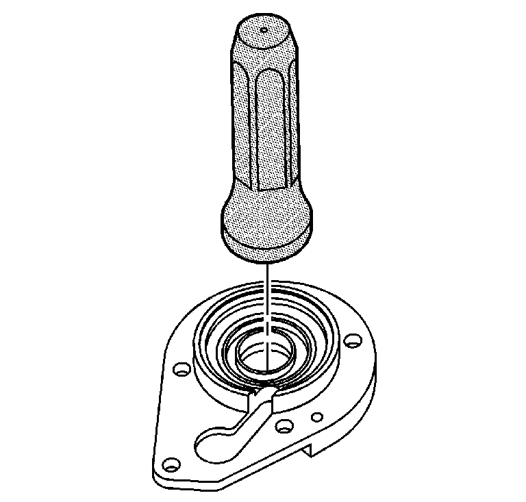
Place the input shaft seal in the front bearing retainer.
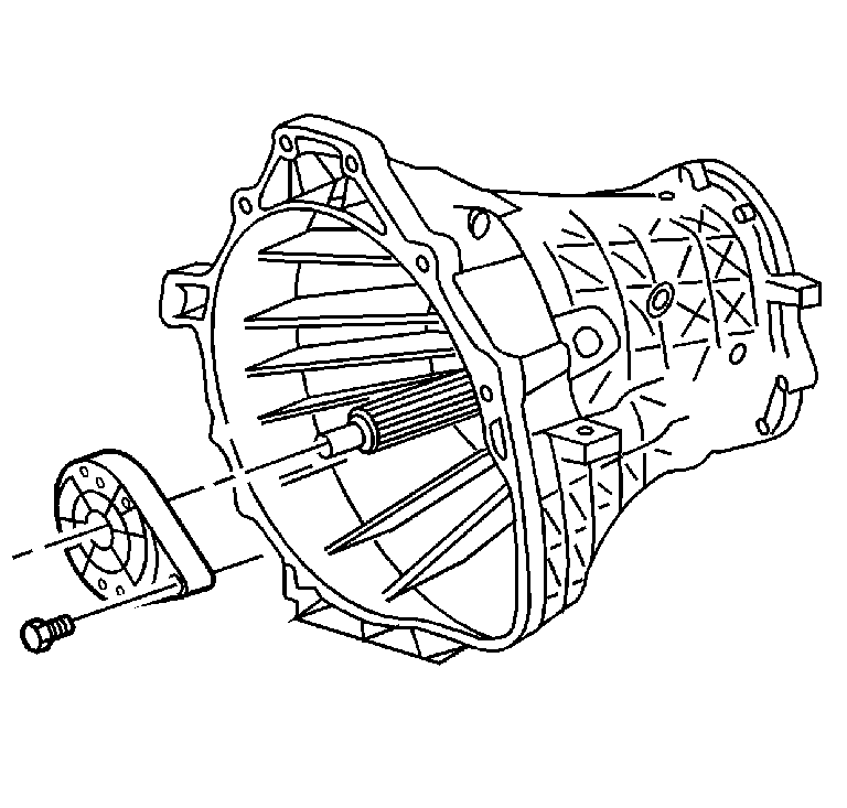
Notice: Use the correct fastener in the correct location. Replacement fasteners must be the correct part number for that application. Fasteners requiring replacement or fasteners requiring the use of thread locking compound or sealant are identified in the service procedure. Do not use paints, lubricants, or corrosion inhibitors on fasteners or fastener joint surfaces unless specified. These coatings affect fastener torque and joint clamping force and may damage the fastener. Use the correct tightening sequence and specifications when installing fasteners in order to avoid damage to parts and systems.
Tighten
Tighten the 5 bearing retainer bolts to 29 N·m (21 lb ft).

Tighten
Tighten the clutch actuator bolts to 8 N·m (71 lb in).
