Cylinder Head Replacement With CTF
Removal Procedure
- Remove the engine cover. Refer to Engine Cover Replacement .
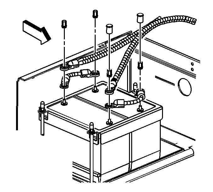
- Disconnect the negative battery cable. Refer to Battery Negative Cable Disconnection and Connection .
- Drain the cooling system. Refer to Cooling System Draining and Filling .
- Remove the charge air inlet pipe. Refer to Charge Air Cooler Inlet Pipe and Outlet Pipe Replacement .
- Remove the exhaust gas recirculation (EGR) pipe. Refer to Exhaust Gas Recirculation Pipe Replacement .
- Remove the EGR valve. Refer to Exhaust Gas Recirculation Valve Replacement .
- Remove the turbocharger assembly. Refer to Turbocharger Replacement .
- Remove the intake manifold assembly. Refer to Intake Manifold Replacement .
- Remove the exhaust manifold assembly. Refer to Exhaust Manifold Replacement .
- Remove the heat shield and bracket.
- Remove the drive belt. Refer to Drive Belt Replacement .
- Remove the cooling fan. Refer to Fan Replacement .
- Remove the turbocharger coolant line retainer from the cylinder head.
- Remove the turbocharger coolant line from the right side of the cooling fan adapter.
- Disconnect the cooling line from the left side of the cooling fan adapter.
- Remove the 5 bolts and the cooling fan adapter from the cylinder head.
- Remove the valve rocker arm cover. Refer to Valve Rocker Arm Cover Replacement .
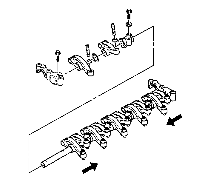
- Remove the valve rocker arm shaft assembly. Refer to Valve Rocker Arm and Shaft Assembly Removal .
- Remove the camshaft assembly. Refer to Camshaft Replacement .
- Remove the fuel injectors. Refer to Fuel Injector Replacement .
- If equipped, remove the coolant line from the air compressor to the cylinder head.
- Remove the glow plugs. Refer to Glow Plug Replacement .
- If equipped, remove the air compressor line bracket from the rear of the cylinder head.
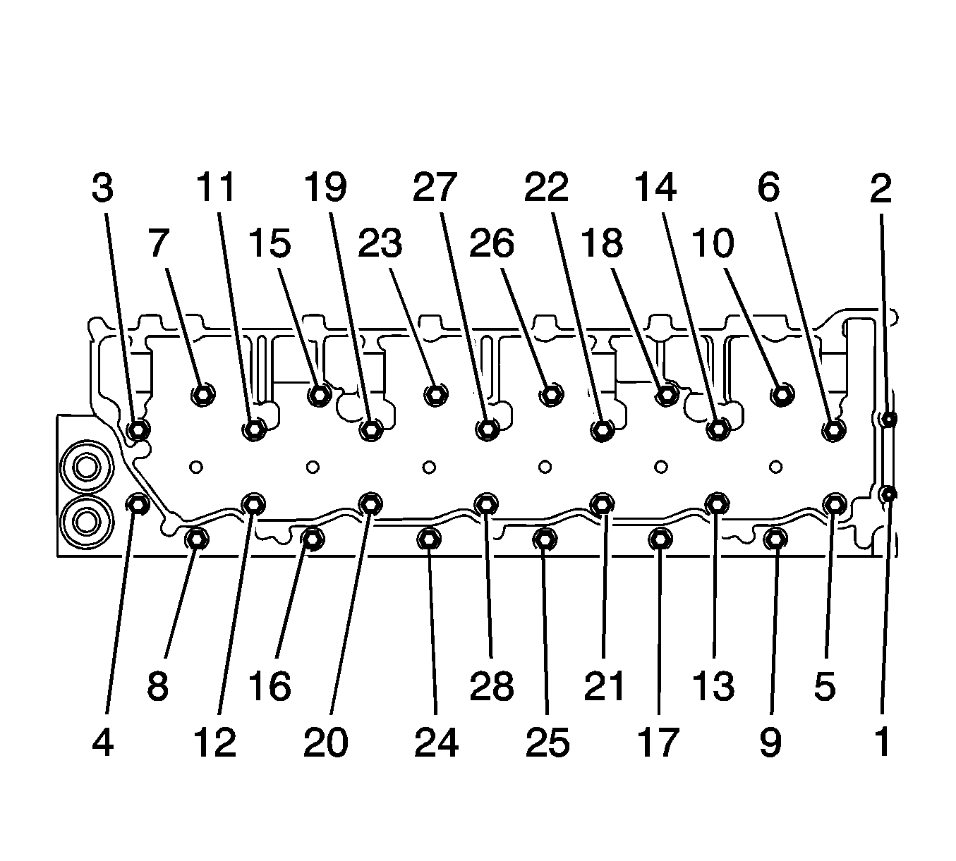
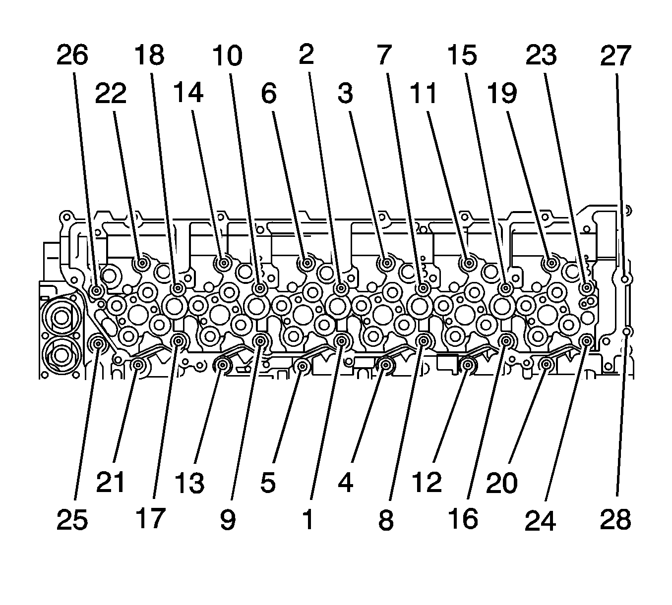
- Remove the cylinder head bolts from the cylinder head in the numerical order shown in the illustration.
- Remove the cylinder head and the gasket from the engine.
- Inspect the threaded parts for wear or damage.
- Clean carbon deposits from the combustion chambers.
- Clean all traces of the old cylinder head gasket from the cylinder head and the engine block.
- Clean the cylinder head bolt threads using a wire brush.
- Clean metal chips and dirt from the threads in the cylinder block.
- Inspect the cylinder head for cracks or damage.

Important: Use a straight edge to inspect the flatness of the cylinder head. If the cylinder head has more than 0.2 mm (0.0078 in) gap between the straight edge and the surface of the cylinder head, replace the cylinder head.
Installation Procedure
- Install the cylinder head and gasket to the block.
- Apply molybdenum grease to the large head bolts (M14 bolts).
- Apply clean engine oil to the small head bolts (M10 bolts).
- Install the cylinder head bolts to the cylinder head.
- Tighten the cylinder head bolts in the following sequence:
- Tighten the remaining cylinder head bolts in the following sequence:
- Install the camshaft assembly. Refer to Camshaft Replacement .
- Install the rocker arm shaft assembly. Refer to Valve Rocker Arm and Shaft Installation .
- Install the valve rocker arm cover. Refer to Valve Rocker Arm Cover Replacement .
- If equipped, install the coolant line from the air compressor to the cylinder head.
- If equipped, install the air compressor lines and the bracket to the rear of the cylinder head.
- Install the glow plugs. Refer to Glow Plug Replacement .
- Install the fuel injectors. Refer to Fuel Injector Replacement .
- Install the exhaust manifold. Refer to Exhaust Manifold Replacement .
- Install the intake manifold. Refer to Intake Manifold Replacement .
- Install the turbocharger assembly. Refer to Turbocharger Replacement .
- Install the EGR valve. Refer to Exhaust Gas Recirculation Valve Replacement .
- Install the EGR pipe. Refer to Exhaust Gas Recirculation Pipe Replacement .
- Install the cooling fan adapter to the cylinder head with 5 bolts.
- Connect the left side coolant line to the cooling fan adapter.
- Using a new gasket, install the turbocharger cooling line to the cooling fan adapter.
- Install the turbocharger cooling line to the cylinder head with clamp and fasteners.
- Install the cooling fan. Refer to Fan Replacement .
- Install the drive belt. Refer to Drive Belt Replacement .
- Install the charge air inlet pipe. Refer to Charge Air Cooler Inlet Pipe and Outlet Pipe Replacement .
- Connect the negative battery cable. Refer to Battery Negative Cable Disconnection and Connection .
- Install the engine cover. Refer to Engine Cover Replacement .
Important: Apply sealant to the rear corners of the cylinder block before installing the cylinder head gasket with the part number facing up.

Notice: Refer to Fastener Notice in the Preface section.
| 5.1. | First pass for bolts 1-26: |
Tighten
Tighten bolts 1-26 to 98 N·m (72 lb ft).
| 5.2. | Second pass for bolts 1-26: |
Tighten
Tighten bolts 1-26 to 147 N·m (108 lb ft).
| 5.3. | Turn bolts 1-26 an additional 30 to 60 degrees. |
Tighten
For bolts 27 and 28 tighten to 38 N·m (28 lb ft).
Tighten
Tighten the cooling line to 25 N·m (34 lb ft).
Cylinder Head Replacement Without CTF
Removal Procedure
- Disconnect the negative battery cable. Refer to Battery Negative Cable Disconnection and Connection in Engine Electrical.
- Remove the charge air inlet pipes. Refer to Charge Air Cooler Inlet Pipe and Outlet Pipe Replacement in Engine Controls - 7.8L.
- Remove the cooling layer. Refer to Cooling Layer Removal in Engine Cooling.
- Remove the intake manifold assembly. Refer to Intake Manifold Replacement .
- Remove the turbocharger assembly. Refer to Turbocharger Replacement in Engine Controls - 7.8L.
- Remove the exhaust manifold assembly. Refer to Exhaust Manifold Replacement in Engine Exhaust.
- Remove the heat shield and bracket.
- Remove the valve rocker arm cover. Refer to Valve Rocker Arm Cover Replacement .
- Remove the drive belt. Refer to Drive Belt Replacement .
- Remove the cooling fan. Refer to Fan Replacement in Engine Cooling.
- Remove the turbocharger coolant line retainer from the cylinder head.
- Remove the turbocharger coolant line from the right side of the cooling fan adapter.
- Disconnect the cooling line from the left side of the cooling fan adapter.
- Remove the 5 bolts and the cooling fan adapter from the cylinder head.
- Remove the valve rocker arm shaft assembly. Refer to Valve Rocker Arm and Shaft Assembly Removal .
- Remove the camshaft assembly. Refer to Camshaft Replacement .
- Remove the fuel injectors. Refer to Fuel Injector Replacement in Engine Controls - 7.8L.
- Remove the coolant line from the air compressor to the cylinder head.
- Remove the glow plugs. Refer to Glow Plug Replacement in Engine Controls - 7.8L.
- Remove the air compressor line bracket from the rear of the cylinder head in the numerical order shown in the illustration.
- Remove the cylinder head bolts from the cylinder head.
- Remove the cylinder head and the gasket from the engine.
- Inspect the threaded parts for wear or damage.
- Clean carbon deposits from the combustion chambers.
- Clean all traces of the old cylinder head gasket from the cylinder head and the engine block.
- Clean the cylinder head bolt threads using a wire brush.
- Clean metal chips and dirt from the threads in the cylinder block.
- Inspect the cylinder head for cracks or damage.


Important: Use a straight edge to inspect the flatness of the cylinder head. If the cylinder head has more than a 0.2 mm (0.0078 in) gap between the straight edge and the surface of the cylinder head, replace the cylinder head.
Installation Procedure
- Install the cylinder head and gasket to the block.
- Apply molybdenum grease to the large head bolts (M14 bolts).
- Apply clean engine oil to the small head bolts (M10 bolts).
- Install the cylinder head bolts to the cylinder head.
- Tighten the cylinder head bolts in the following sequence:
- Tighten the remaining cylinder head bolts in the following sequence:
- Install the camshaft assembly. Refer to Camshaft Replacement .
- Install the rocker arm shaft assembly. Refer to Valve Rocker Arm and Shaft Installation .
- Install the valve rocker arm cover. Refer to Valve Rocker Arm Cover Replacement .
- If equipped, install the coolant line from the air compressor to the cylinder head.
- If equipped, install the air compressor lines and the bracket to the rear of the cylinder head.
- Install the glow plugs. Refer to Glow Plug Replacement in Engine Controls - 7.8L.
- Install the fuel injectors. Refer to Fuel Injector Replacement in Engine Controls - 7.8L.
- Install the exhaust manifold. Refer to Exhaust Manifold Replacement in Engine Exhaust.
- Install the turbocharger assembly. Refer to Turbocharger Replacement in Engine Controls - 7.8L.
- Install the intake manifold. Refer to Intake Manifold Replacement .
- Install the cooling fan adapter to the cylinder head with 5 bolts.
- Connect the left side coolant line to the cooling fan adapter.
- Using a new gasket, install the turbocharger cooling line to the cooling fan adapter.
- Install the turbocharger cooling line to the cylinder head with clamp and fasteners.
- Install the cooling fan. Refer to Fan Replacement in Engine Cooling.
- Install the drive belt. Refer to Drive Belt Replacement .
- Install the charge air inlet pipe. Refer to Charge Air Cooler Inlet Pipe and Outlet Pipe Replacement in Engine Controls - 7.8L.
- Connect the negative battery cable. Refer to Battery Negative Cable Disconnection and Connection in Engine Electrical.
- Install the cooling layer. Refer to Cooling Layer Installation in Engine Cooling.
Important: Apply sealant to the rear corners of the cylinder block before installing the cylinder head gasket with the part number facing up.

Notice: Refer to Fastener Notice in the Preface section.
| 5.1. | First pass for bolts 1-26: |
Tighten
Tighten bolts 1-26 to 98 N·m (72 lb ft).
| 5.2. | Second pass for bolts 1-26: |
Tighten
Tighten bolts 1-26 to 147 N·m (108 lb ft).
| 5.3. | Turn bolts 1-26 an additional 30 to 60 degrees. |
Tighten
For bolts 27 and 28 tighten to 38 N·m (28 lb ft).

Tighten
Tighten the cooling line to 25 N·m (34 lb ft).

