For 1990-2009 cars only
Two-Piece Rear Propeller Shaft Replacement Two Piece-Rear
Removal Procedure
- Block the wheels.
- Support the propeller shaft.
- Mark the universal joints and slip joints with alignment marks.
- Remove the propeller shaft guards, if equipped.
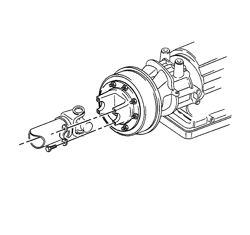
- Remove the propeller shaft from the brake drum.
- Remove the two-piece propeller shaft with tandem axle mounting.
- Remove the propeller shaft.
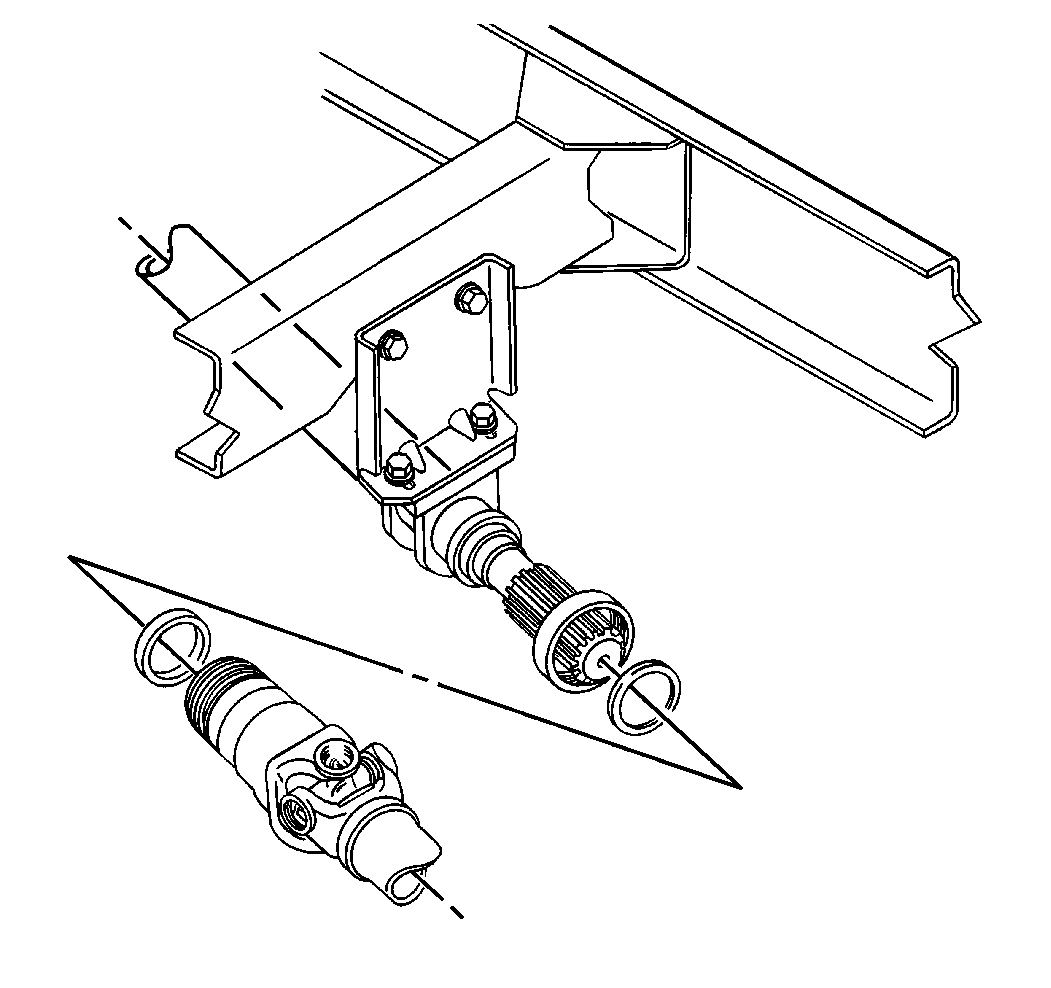
- Remove the center bearing assembly from the cross member. Refer to Propeller Shaft Center Support Bearing Replacement.


Installation Procedure
- Install NEW universal joints to propeller shaft. Refer to Universal Joint Replacement and Universal Joint Replacement - External Snap Ring.
- Support the propeller shaft sections in the installed position.
- Install the slip yoke and the center bearing assembly to the installed propeller shaft splined end. Refer to the following procedures:
- Install the front propeller shaft to the brake drum. Keep the alignment marks together.
- Install and tighten the propeller shaft round end yoke bolts. Refer to Fastener Tightening Specifications.
- Inspect the propeller shaft for alignment and phasing.
- Install the propeller shaft guards, if equipped.
- Lubricate the universal joints and the slip joints. Refer to Propeller Shaft Assembly Component Lubrication.
- Remove the wheel blocks.

Caution: Refer to Fastener Caution in the Preface section.

Two-Piece Rear Propeller Shaft Replacement Two Piece-FRX
Removal Procedure
- Block the wheels.
- Support the propeller shaft.
- Mark the universal joints and slip joints with alignment marks.
- Remove the propeller shaft guards, if equipped.
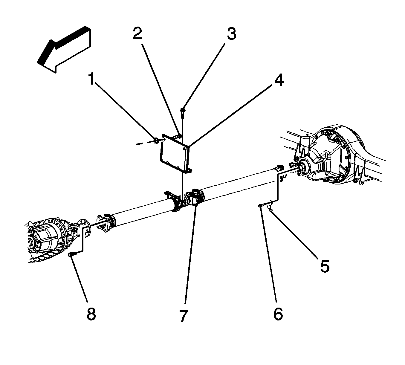
- Remove the propeller shaft transfer case flange bolts (8).
- Remove the center bearing assembly from the crossmember bracket (4). Refer to Propeller Shaft Center Support Bearing Replacement.
- Remove the propeller shaft retainers (5) and bolts (6).
- Remove the propeller shaft.


Installation Procedure
- Install NEW universal joints to propeller shaft. Refer to Universal Joint Replacement - External Snap Ring.
- Support the propeller shaft sections in the installed position and align the marks.
- Install the propeller shaft retainers (5) and bolts (6).
- Install the center bearing assembly to the crossmember bracket (4). Refer to Propeller Shaft Center Support Bearing Replacement.
- Install the propeller shaft transfer case flange bolts (8).
- Install the propeller shaft guards, if equipped.
- Lubricate the universal joints and the slip joints. Refer to Fluid and Lubricant Recommendations.
- Remove the wheel blocks.

Caution: Refer to Fastener Caution in the Preface section.
Tighten
Tighten to 66 N·m (49 lb ft).
Tighten
Tighten to 97 N·m (72 lb ft).

