Removal Procedure
Tools Required
J 41427 Engine Lift
Brackets
- Disconnect the battery negative cable. Refer to
Battery Cable
in Engine Electrical.
- Remove the hood. Refer to
Hood Replacement
in Body Front End.
- Remove the air cleaner assembly. Refer to
Air Cleaner Assembly Replacement
in Engine Controls 5.0, 5.7L
- Drain the engine coolant. Refer to
Cooling System Draining and Filling
in Engine Cooling.
- Remove the following coolant hoses:
- Remove the upper radiator shroud. Refer to
Fan Shroud Replacement
in Engine Cooling.
- Remove the drive belt. Refer to
Drive Belt Replacement
.
Caution: In order to avoid possible injury or vehicle damage, always replace
the accelerator control cable with a NEW cable whenever you remove the engine
from the vehicle.
In order to avoid cruise control cable damage, position the cable out
of the way while you remove or install the engine. Do not pry
or lean against the cruise control cable and do not kink the cable. You must
replace a damaged cable.
- Disconnect the accelerator control cable and the cruise control cable,
if equipped. Refer to Accelerator Controls Cable Replacement
in Engine Controls 5.0, 5.7L
- Remove the engine cooling fan. Refer to
Fan Clutch Replacement
in Engine Cooling.
Important: It is not necessary to discharge the A/C refrigerant.
- Remove the air conditioning compressor, if equipped, and set it aside.
Refer to
Air Conditioning Compressor Replacement
in
Heating, Ventilation and Air Conditioning.
- Remove AIR bypass hose assembly, if so equiped. Refer to
Secondary Air Injection Check Valve and Check Valve Pipe Replacement
in Engine Controls.
- Remove the power steering pump pulley. Refer to
Power Steering Pump Replacement
in Power Steering.

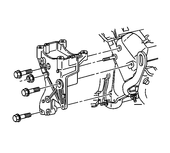
- Remove the power steering
pump mounting bracket. Refer to
Accessory Mounting Brackets Replacement
.
- Set the power steering pump and the mounting bracket aside.
- Remove the starter motor. Refer to
Starter Motor Replacement
.
- Disconnect the positive battery cable at the generator. Refer
to
Generator Replacement
in Engine
Electrical.
- Remove the torque converter to flywheel bolts.
- Disconnect the transmission cooler pipe bracket from the right
side of the oil pan. Refer to
Oil Cooler Hose/Pipe Replacement
in automatic transmission, transaxle.
- Remove the exhaust pipe from the exhaust manifolds. Refer to
Exhaust Crossover Pipe Replacement
in Engine
Exhaust.
- Support the transmission with a suitable strap.
- Remove the engine oil cooler pipes, if equipped. Refer to
Oil Cooler Hose/Pipe Replacement
.

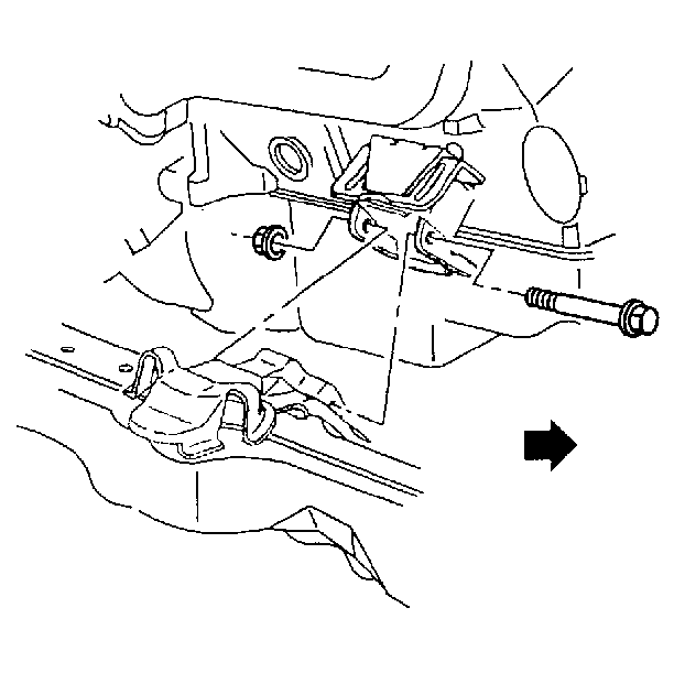
- Remove both engine mount
through-bolts.
- Remove seven transmission to engine bolts including the brackets.
- Lower the vehicle.
- Disconnect the remaining electrical connectors.
- Remove the distributor cap. Refer to
Distributor Replacement
.
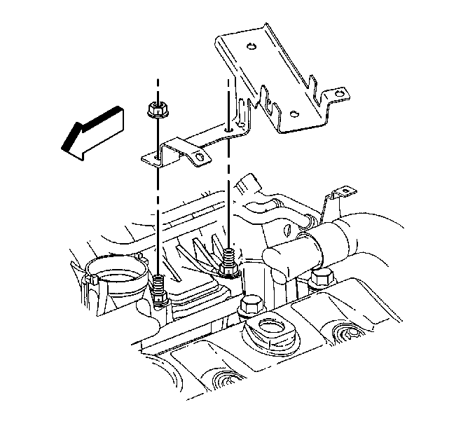
- Remove the engine harness support.
- Disconnect the fuel pipes. Refer to
Fuel Hose/Pipes Replacement - Engine Compartment
in Engine Controls
5.0, 5.7L.
- Remove two transmission to engine bolts at the rear top of the
engine.
- Remove the EGR pipe. Refer to
Secondary Air Injection Check Valve and Check Valve Pipe Replacement
in Engine Controls
5.0, 5.7L.

Notice: Use the correct fastener in the correct location. Replacement fasteners
must be the correct part number for that application. Fasteners requiring
replacement or fasteners requiring the use of thread locking compound or sealant
are identified in the service procedure. Do not use paints, lubricants, or
corrosion inhibitors on fasteners or fastener joint surfaces unless specified.
These coatings affect fastener torque and joint clamping force and may damage
the fastener. Use the correct tightening sequence and specifications when
installing fasteners in order to avoid damage to parts and systems.
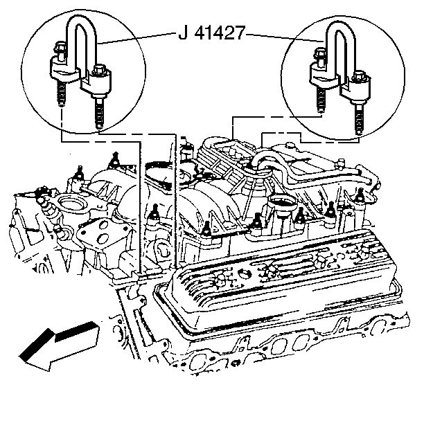
- Attach the lift
bracketsJ 41427
to the
left front and right rear intake manifold mounting bolts, using the following
procedure:
| 31.2. | Install the lift bracket J 41427
marked RIGHT REAR. |
| 31.3. | Install the retaining bolts. |
Tighten
Tighten the bolts to 15 N·m (11 lb in).
| 31.5. | Install the J 41427
marked LEFT FRONT with the arrow pointing to the front of the engine. |
| 31.6. | Install the retaining bolts. |
Tighten
Tighten the bolts to 15 N·m (11 lb in).
- Attach a suitable lifting device to the lift brackets.
- Remove the engine.
Installation Procedure

- Install the engine in
the vehicle.
- Install two top transmission to engine bolts, including the brackets
and clips.
- Remove the J 41427
and the lifting device.
- Apply thread lock GM P/N 12345382 or equivalent
to the threads of the lower intake manifold bolts.
- Install the intake manifold. Refer to
Intake Manifold Replacement
.
- Install the EGR valve inlet pipe. Refer to
Secondary Air Injection Check Valve and Check Valve Pipe Replacement
in
Engine Controls 5.0, 5.7L.
- Connect the fuel pipes. Refer to
Fuel Hose/Pipes Replacement - Engine Compartment
in Engine Controls
5.0, 5.7L.
Notice: Use the correct fastener in the correct location. Replacement fasteners
must be the correct part number for that application. Fasteners requiring
replacement or fasteners requiring the use of thread locking compound or sealant
are identified in the service procedure. Do not use paints, lubricants, or
corrosion inhibitors on fasteners or fastener joint surfaces unless specified.
These coatings affect fastener torque and joint clamping force and may damage
the fastener. Use the correct tightening sequence and specifications when
installing fasteners in order to avoid damage to parts and systems.
- Install the engine
harness support.
Tighten
Tighten the nut to 12 N·m (106 lb in).
- Install the distributor cap. Refer to
Distributor Replacement
in Engine Electrical.
- Install the AIR bypass hose assembly, if equiped. Refer to
Secondary Air Injection Check Valve and Check Valve Pipe Replacement
in Engine Controls 5.0, 5.7L.
- Install the transmission to engine bolts.

- Install both engine mount
through-bolts, if equipped. Refer to
Engine Mount Replacement
.
- Install the oil cooler pipes, if equipped. Refer to
Oil Cooler Hose/Pipe Replacement
in Engine Cooling.
- Remove the transmission support strap.
- Install the exhaust pipe to the exhaust manifolds. Refer to
Exhaust Manifold Pipe Replacement
in Engine Exhaust.
- Install the transmission cooler pipe bracket to the right side
of the oil pan, if equipped. Refer to
Oil Cooler Hose/Pipe Replacement
.
- Install three torque convertor to engine flywheel bolts, if equipped.
- Install the starter motor. Refer to
Starter Motor Replacement
.
- Connect the positive battery cable at the generator. Refer to
Generator Replacement
in Engine Electrical.

- Install the power steering
pump mounting bracket. Refer to
Accessory Mounting Brackets Replacement
in Power Steering System.
- Install the air conditioning (A/C) compressor, if equipped. Refer
to
Air Conditioning Compressor Replacement
in Heating,
Ventilation and Air Conditioning.
- Use the J 25033-C
in order to install the power steering pump pulley. Refer to
Power Steering Pump Replacement
in Power Steering System.
- Install the engine cooling fan. Refer to
Fan Clutch Replacement
in Engine Cooling.
- Install the drive belt. Refer to
Drive Belt Replacement
.
Caution: In order to avoid possible injury or vehicle damage, always replace
the accelerator control cable with a NEW cable whenever you remove the engine
from the vehicle.
In order to avoid cruise control cable damage, position the cable out
of the way while you remove or install the engine. Do not pry
or lean against the cruise control cable and do not kink the cable. You must
replace a damaged cable.
- Connect the NEW accelerator control cable and the cruise control cable,
if equipped. Refer to Accelerator Controls Cable Replacement
in Engine Controls 5.0, 5.7L.
- Install the air cleaner assembly. Refer to
Air Cleaner Assembly Replacement
in Engine Controls 5.0, 5.7L.
- Install the upper radiator shroud. Refer to
Fan Shroud Replacement
in Engine Cooling.
- Install the following coolant hoses:
- Fill the cooling system with coolant. Refer to
Cooling System Draining and Filling
in Engine Cooling.
- Install the hood. Refer to
Hood Replacement
.
- Connect the battery negative cable. Refer to
Battery Cable
in Engine Electrical.
- Before starting a new engine, or one that has been repaired. Refer
toEngine Set-Up and Testing
.
- The final step is to perform the CKP System Variation Learn procedure.
Refer to
Crankshaft Position System Variation Learn
in Engine Controls 5.0, 5.7L.


