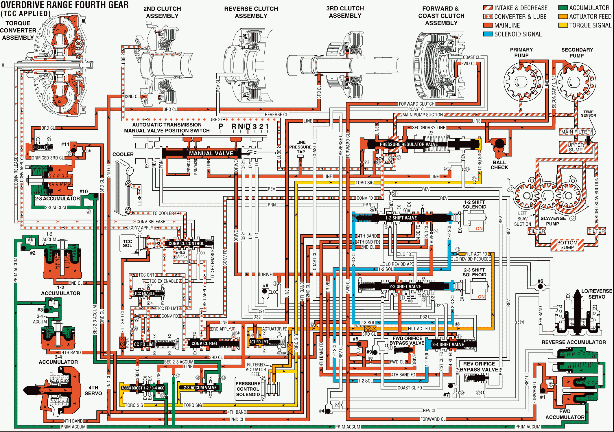
The torque converter clutch applies during fourth gear operation after the Powertrain Control Module (PCM) receives the appropriate input signals to energize the torque converter clutch (TCC) solenoid. To apply the torque converter clutch, the following changes take place in the electrical and hydraulic systems:
Torque Converter Clutch (TCC) Solenoid
When the TCC solenoid is energized (turned ON), this three-port, pulse width modulation (PWM) solenoid operates on a negative duty cycle at a fixed frequency of 32 Hz. The PCM controls the duty cycle (on time verses off time) based on vehicle operating conditions to enable a smooth apply of the torque converter clutch. Filtered third clutch fluid acts on one end of the solenoid. This forces the converter clutch control valve to shift against the opposing force of the spring.
Converter Clutch Control Valve
When filtered third clutch fluid acts on the end of the converter clutch control valve, the valve is shifted. Filtered third clutch fluid enters the TCC control circuit. However, the PWM action of the TCC solenoid controls the fluid pressure entering the TCC control fluid passage from the third clutch. TCC control fluid pressure is then routed to the converter clutch regulating valve and to the TCC enable valve.
Converter Clutch Regulating Valve
The converter clutch regulating valve is biased by TCC control fluid pressure, by spring force, and by orificed apply fluid. The valve regulates line pressure entering the regulated apply circuit. Regulated apply fluid is routed to the converter clutch control valve and through orifice #34, where the fluid enters the orificed apply fluid passage. Orifice apply fluid is then routed to the spring side of the converter clutch regulating valve.
Converter Clutch Control Valve
When the valve is shifted against spring force, regulated apply fluid (from the converter clutch regulating valve) enters the converter apply circuit. Converter apply fluid is then routed to the apply side of the torque converter pressure plate. TCC feed limit fluid, previously feeding into the converter release circuit, passes through the valve and enters the circuit which directs the fluid to the cooler.
TCC Enable Valve
When shifted by TCC control fluid pressure against spring force, the TCC enable valve prevents the TCC feed limit from entering the orificed TCC exhaust enable passage.
Important: After the transmission is operating with the torque converter clutch applied, the cooler and the lubrication circuits function in the same manner as previously explained. Refer to Reverse . Release fluid is then exhausted through the TCC enable valve.
Overdrive Range, Fourth Gear - TCC Applied

