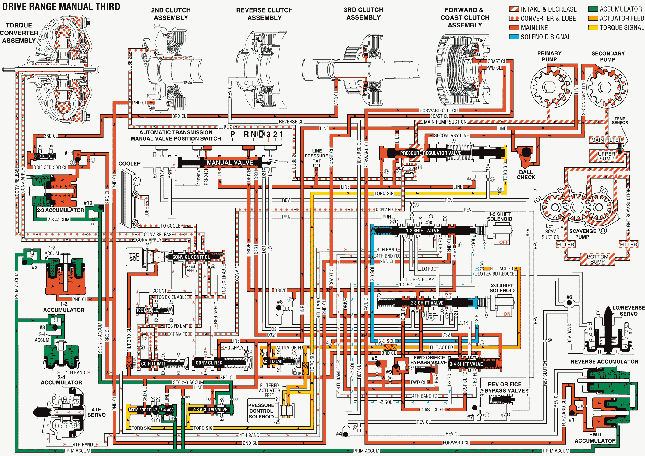
When the gear selector lever is moved to the Drive Range (3) position, the manual valve also moves. This allows line pressure to enter the D321 fluid circuit. The torque converter clutch releases in the same manner as previously described. Refer to Overdrive Range, Fourth Gear - Torque Converter Clutch Applied , but the torque converter clutch may reapply when the appropriate operating conditions of the vehicle have been met.
Coast Clutch Applies
Manual Valve
Mechanically moved through the gear selection, the manual valve allows line pressure to enter the D321 fluid circuit, and the PRDN4 fluid exhausts at the valve. D321 fluid is then routed to the spring end of the 3-4 shift valve.
3-4 Shift Valve
Spring force and D321 fluid pressure hold the 3-4 shift valve in the downshifted position. The 3-4 shift valve allows D321 fluid to pass through the valve and enter the coast clutch feed circuit. Coast clutch feed is then routed to checkball #9.
#9 Checkball (Coast Clutch Feed, Orificed Coast Clutch Feed)
The #9 checkball is located in the valve body, and the checkball is unseated by coast clutch feed. The checkball routes fluid through orifice #7, where the fluid enters the coast clutch circuit. Coast clutch fluid is then routed to the 2-3 shift valve.
2-3 Shift Valve
High fluid pressure at the 2-3 shift solenoid (SS) valve holds the 2-3 shift valve in the upshifted position. This allows coast clutch fluid to pass through the valve. Coast clutch fluid is then routed to the coast clutch piston and applies the clutch.
Automatic Transmission Manual Valve Position Switch
PRND4 fluid at the PRND4 indicator switch exhausts in order to open its electrical circuit to the PCM. The open circuit is a signal to the PCM that the operator of the vehicle has selected Manual Third gear range.
Fourth Band Releases
1-2 Shift Solenoid (SS) Valve
The 1-2 SS valve de-energizes (turns OFF), allowing the 1-2 SS valve fluid pressure (acting on the end of the 3-4 shift valve) to exhaust through the solenoid. Low fluid pressure acts on the solenoid valve fluid circuit. Spring force, acting on the opposite end of the valve, forces the 3-4 shift valve to move.
Fourth Servo Assembly
Spring force actuates the fourth servo piston. This force returns the piston to its band released position. This movement forces fourth band fluid from the other side of the piston. The fluid is forced back through its circuit to the 1-2 shift valve.
1-2 Shift Valve
Spring force and pressure from the 2-3 shift solenoid (SS) valve hold the 1-2 shift valve in the upshifted position. The fourth band fluid is routed back through the valve and into the fourth band feed circuit. Fourth band feed is then routed to the 3-4 shift valve.
3-4 Shift Valve
Spring force and D321 fluid hold the 3-4 shift valve in the downshifted position. Fourth band fluid from the 1-2 shift valve is routed through the valve into the orificed D21Y fluid passage. Orificed D21Y fluid is then routed through the 2-3 shift valve, where the fluid exhausts.
Manual Third Gear

