For 1990-2009 cars only
Tools Required
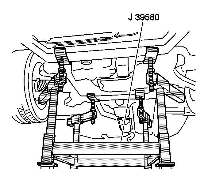
J 39580 Power Pack Stand Engine and Transaxle Assembly Support Remover/Installer
Removal Procedure
- Install the engine support fixture. Refer to Engine Support Fixture for the 3.8L engine or Engine Support Fixture for the 3.6L (LY7) engine.
- Raise and support the vehicle. Refer to Lifting and Jacking the Vehicle .
- Remove the front tires and wheels. Refer to Tire and Wheel Removal and Installation .
- Remove and discard the 2 plastic braces from the front of the radiator lower air deflector. The plastic braces are directly below the front cradle bolts.
- Remove the positive battery cable and the retainers from the frame and position aside. Refer to Battery Positive Cable Replacement .
- Disconnect any power steering hoses from the frame.
- Secure the power steering return hose.
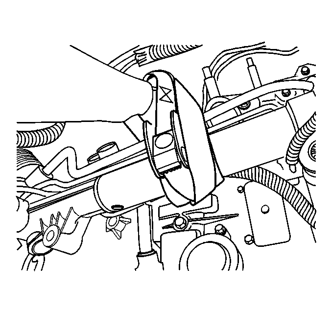
- Remove the stabilizer shaft links and rotate the stabilizer shaft upward to gain access to the mounting bolts in the power steering gear. Refer to Stabilizer Shaft Link Replacement .
- Remove the mounting bolts from the power steering gear. Refer to Steering Gear Replacement .
- Secure the power steering gear.
- Remove the nuts that secure the engine mount to the frame. Refer to Engine Front Mount Replacement for the 3.8L engine or Engine Mount Replacement - Right Side for the 3.6L engine .
- Remove the nuts which secure the transaxle mount to the frame. Refer to Transmission Mount Replacement - Left Side .
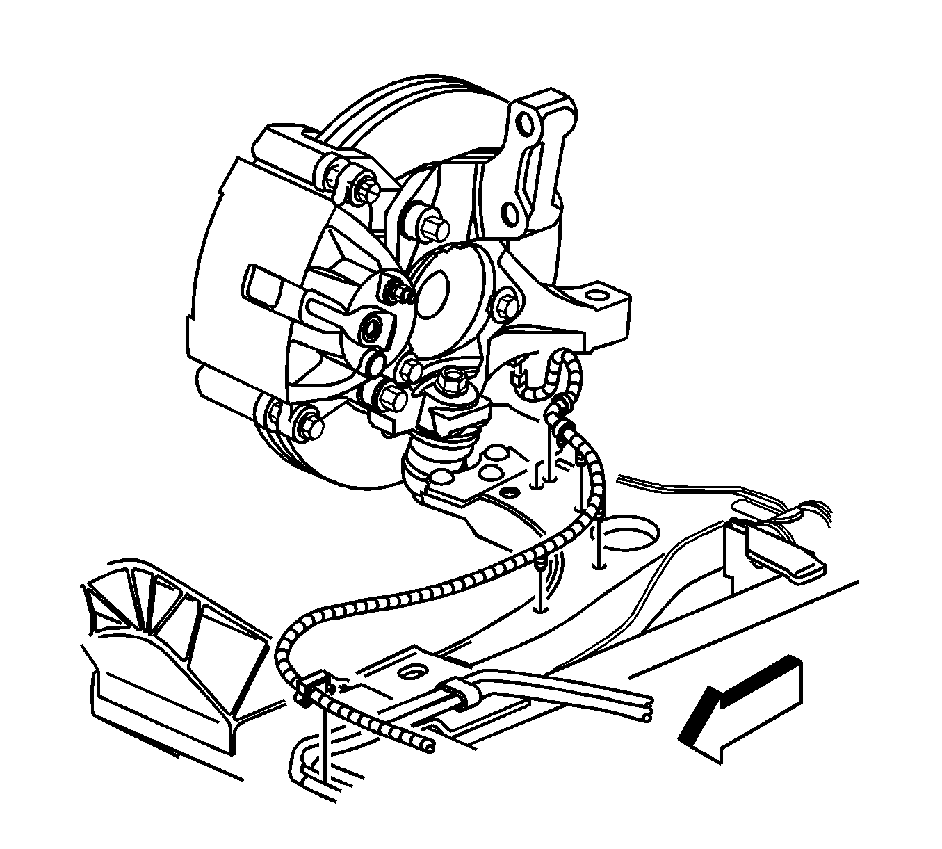
- If applicable, disconnect the front wheel speed sensor harness connectors.
- If applicable, disconnect the wheel speed sensor harness from the frame and lower control arms.
- If applicable, remove the retainers at the front wheel speed harness from the frame and from the lower control arms.
- Separate both of the lower ball joints from the steering knuckle. Refer to Lower Control Arm Replacement .
- Remove both front drivetrain reinforcements using the following procedure.
- Lower the vehicle until the frame contacts the J 39580 .
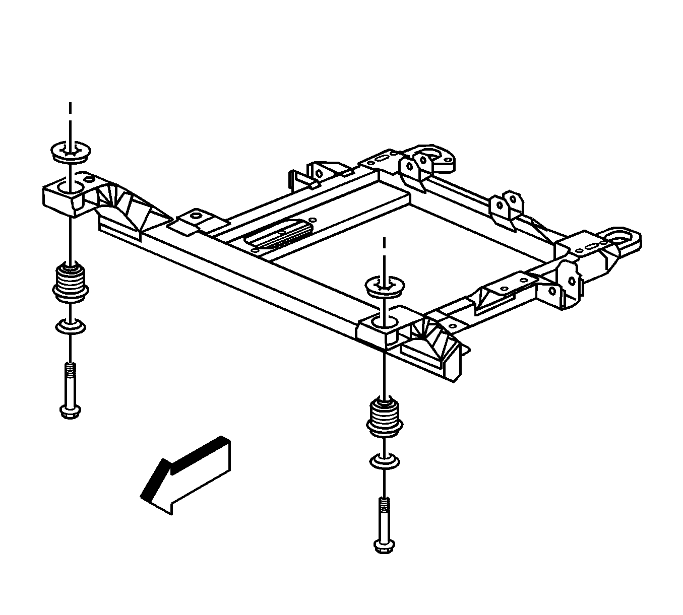
- Remove the bolts which secure the front frame to the body.
- Remove the bolts which secure the rear frame to the body.
- Raise the vehicle in order to separate the frame from the body.
- If you are replacing the frame, remove the following components:
| 17.1. | Remove the drivetrain reinforcement to support brace bolts. |
| 17.2. | Remove the drivetrain reinforcement to front cradle mounting stud nut. |
| 17.3. | Remove the drivetrain reinforcement from the vehicle. |
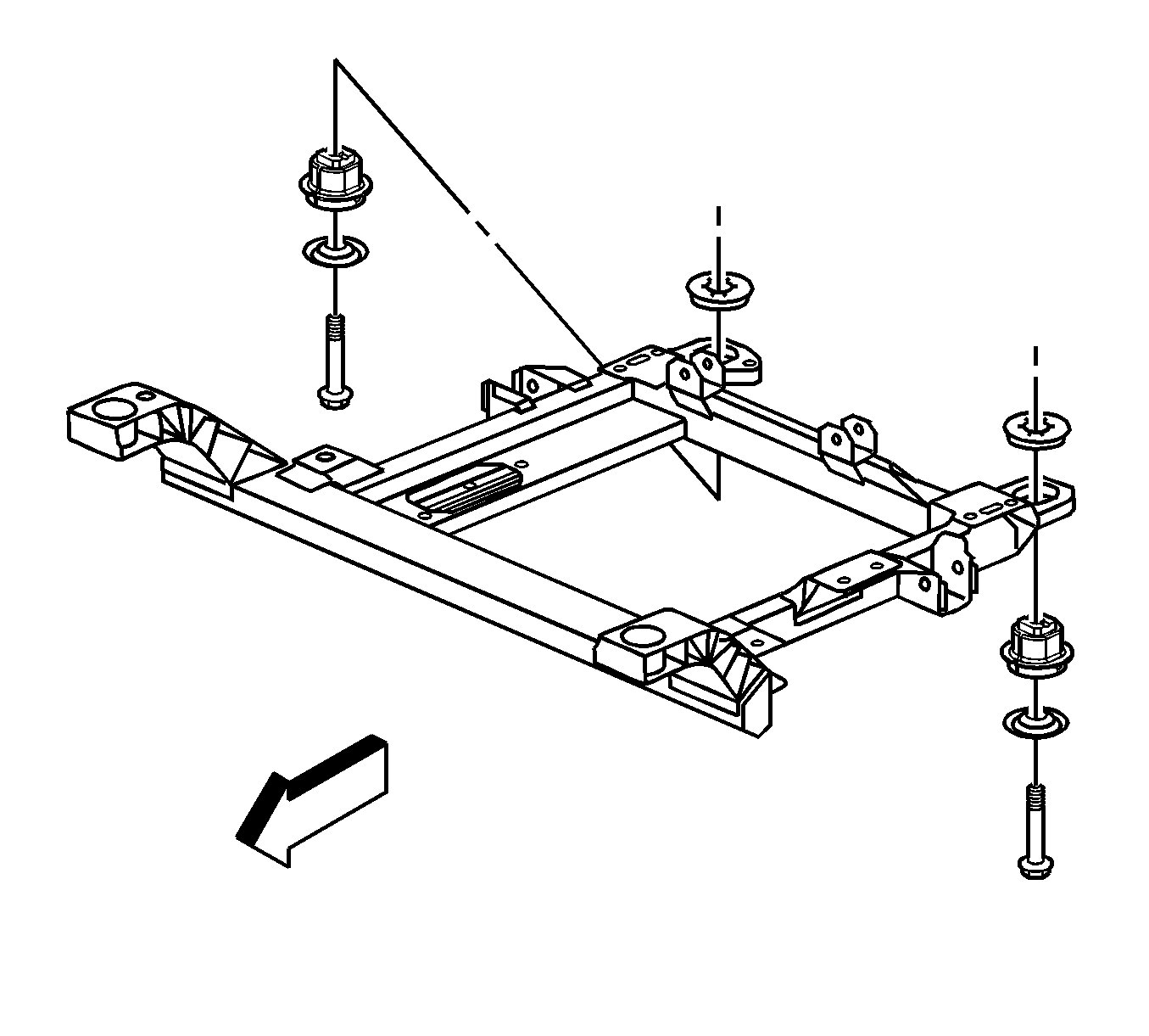
| • | Both of the lower control arms--Refer to Lower Control Arm Replacement . |
| • | The stabilizer shaft--Refer to Stabilizer Shaft Replacement . |
| • | The spacers, the upper insulator, the lower insulator, and the retainers--Refer to Front Frame Cushion or Insulator Replacement or to Rear Frame Cushion or Insulator Replacement . |
Installation Procedure
- If you are replacing the frame, install the following components:
- Position the engine support table with the frame under the vehicle.
- Lower the vehicle to the frame.
- Loosely install the bolts to secure the rear frame to the body.
- Loosely install the bolts to secure the front frame to the body.
- Align the frame to the body by inserting two 19 X 203 mm (0.74 X 8 in) pins in the alignment holes on the right side of the frame.
- Install the front and rear frame bolts.
- Install the drivetrain reinforcements using the following procedure:
- Connect both the lower ball joints to the steering knuckle. Refer to Lower Control Arm Ball Joint Replacement .
- Install the nuts that secure the engine mount to the frame. Refer to Engine Front Mount Replacement for the 3.8L engine or Engine Mount Replacement - Right Side for the 3.6L engine.
- Install the nuts which secure the transaxle mount to the frame. Refer to Transmission Mount Replacement - Left Side .
- Install the steering gear mounting bolts. Refer to Steering Gear Replacement .
- Install the stabilizer shaft links. Refer to Stabilizer Shaft Link Replacement .
- If applicable, connect the wheel speed sensor wiring harness to the frame and lower control arm.
- If applicable, connect the front wheel speed sensor connectors (1).
- If applicable, install the front wheel speed harness retainers (2) to the frame and to the lower control arm.
- Install the positive battery cable and retainers to the frame. Refer to Battery Positive Cable Replacement .
- Connect any power steering hoses to the frame.
- Connect the fog lamp harness connectors.
- Install the front tires and wheels. Refer to Tire and Wheel Removal and Installation .
- Lower the vehicle.
- Remove the engine support fixture. Refer to Engine Support Fixture for the 3.8L engine or Engine Support Fixture for the 3.6L (LY7) engine.
- Inspect the front wheel alignment. Refer to Wheel Alignment Measurement .

| • | Both of the lower control arms--Refer to Lower Control Arm Replacement . |
| • | The stabilizer shaft--Refer to Stabilizer Shaft Replacement . |
| • | The spacers, the upper insulator, the lower insulator, and the retainers--Refer to Front Frame Cushion or Insulator Replacement or to Rear Frame Cushion or Insulator Replacement . |


Notice: Refer to Fastener Notice in the Preface section.
Tighten
| • | Tighten the front bolts to 145 N·m (107 lb ft). |
| • | Tighten the rear bolts to 160 N·m (118 lb ft). |
| 8.1. | Position the drivetrain reinforcements to the font cradle mount stud to the support brace. |
| 8.2. | Loosely install the drivetrain reinforcement to support brace bolts. |
| 8.3. | Install the drivetrain reinforcement to cradle mount nut. |
Tighten
| • | Tighten the drivetrain reinforcement brace nut to 50 N·m (37 lb ft). |
| • | Tighten the drivetrain reinforcement brace bolts to 25 N·m (18 lb ft). |

