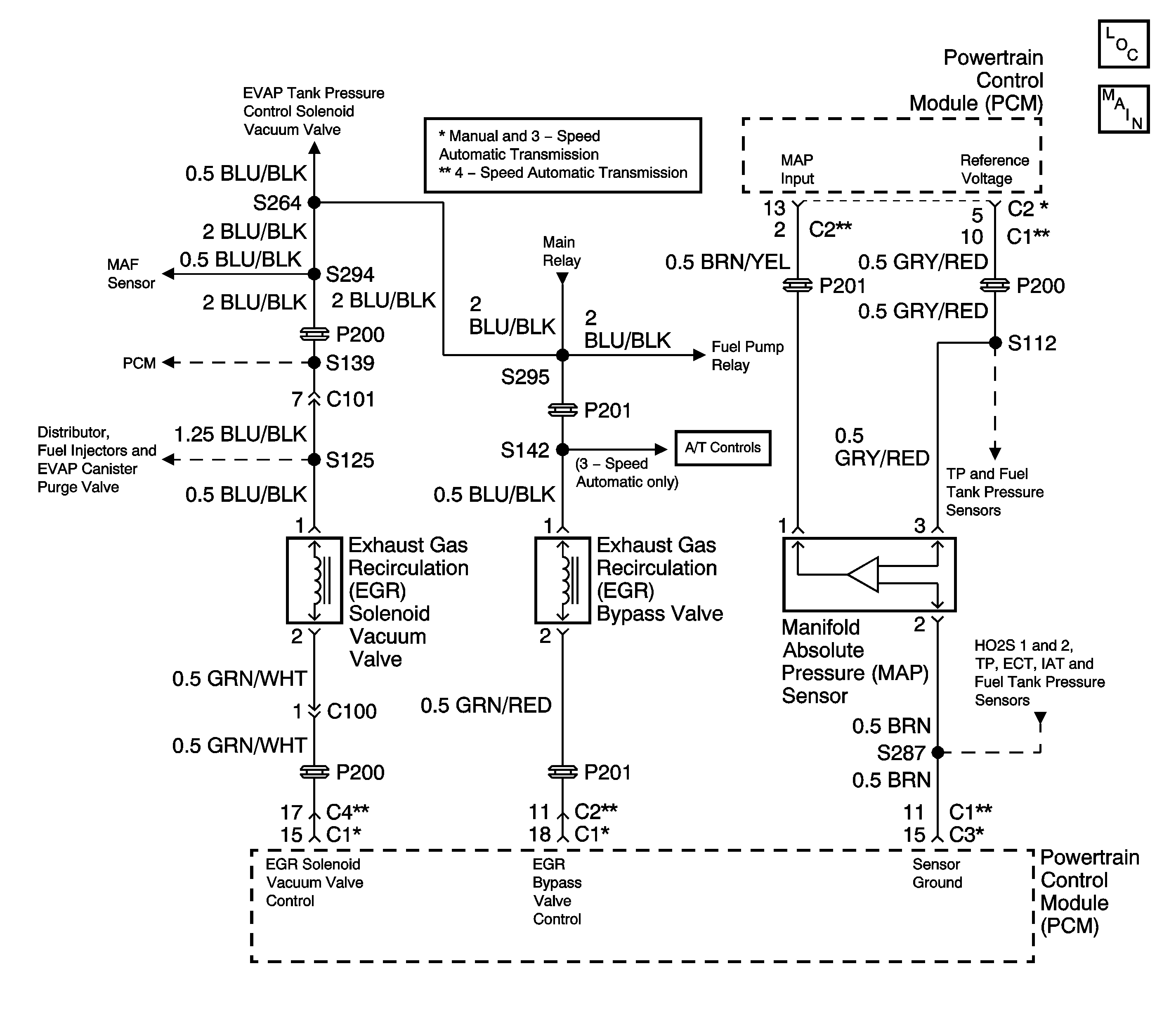
Circuit Description
The exhaust gas recirculation (EGR) system controls the formation of NOx (Oxides of Nitrogen) emissions by recirculating the exhaust gases into the combustion chamber. The powertrain control module (PCM) uses the expected changes in the manifold absolute pressure (MAP) sensor readings in order to evaluate the performance of the EGR system. The PCM applies full manifold vacuum to the EGR valve while monitoring the MAP sensor signal. The PCM suspects that the EGR valve flow is incorrect when the monitored MAP sensor pressure change is either too large or too small.
Conditions for Running the DTC
| • | Engine coolant temperature is between 75°C and 110°C (167°F and 230°F). |
| • | Intake air temperature is between -7°C and 70°C (19°F and 158°F). |
| • | Barometric pressure is greater than or equal to 75 kPa. |
Conditions for Setting the DTC
Intake pressure change during steady state driving conditions (EGR valve is OPEN):
| • | Engine speed is between: |
| - | 1,500 and 3,000 RPM (A/T) |
| - | 2,300 and 4,000 RPM (M/T) |
| • | Vehicle speed is greater than 32 km/h (20 mph). |
| • | Engine speed change less than 150 RPM / 25 msec. |
| • | The change in throttle position is less than 0.37 degrees / 5 msec. |
| • | The EGR valve is commanded CLOSED as the intake pressure difference diagnostic runs for 2 seconds, once per drive cycle. |
| • | The intake pressure difference diagnostic indicates that EGR flow is more than expected or less than expected. |
Intake pressure change during deceleration (EGR valve is CLOSED):
| • | Initial engine speed is between 1,500 and 4,000 RPM. |
| • | Initial vehicle speed is greater than 46 km/h (28 mph). |
| • | After 290 seconds from engine start in fuel shut-off mode. |
| • | The EGR valve is commanded OPEN as the intake pressure difference diagnostic runs for 2 seconds, once per drive cycle. |
| • | The intake pressure difference diagnostic indicates that EGR flow is less than expected. |
Action Taken When the DTC Sets
| • | The PCM illuminates the malfunction indicator lamp (MIL) after two consecutive ignition cycles in which the diagnostic runs with the fault active. |
| • | The PCM records the operating conditions at the time the diagnostic fails. This information is stored in the Freeze Frame buffer. |
Conditions for Clearing the MIL/DTC
| • | The MIL turns OFF after three consecutively passing trips without a fault present. |
| • | A History DTC clears after 40 consecutive warm-up cycles without a fault. |
| • | Use the scan tool Clear DTC Information function or disconnect the PCM battery feed in order to clear the DTC. |
Diagnostic Aids
Normal engine operating temperature is specified as 80°C (176°F) or above.
A DTC P0400 is more likely to set during a combination of highway and city driving. Operate the vehicle in stop and go situations with short trips on the highway in order to validate a DTC P0400.
Perform the scan tool Clear DTC Information function. Road test the vehicle while monitoring the EGR System test in the MIL/System Status selection under System Information on the scan tool. When the EGR System test indicates complete with a YES status, check for a DTC P0400 under Last Test Failed. If there is no DTC P0400 indicated, the DTC is intermittent and the EGR System diagnostic is indicating OK at this time.
Check for any of the following conditions:
| • | A blocked or leaking exhaust manifold to EGR pressure transducer hose |
| • | Faulty vacuum hose connections |
| • | Leaking, deteriorated, or blocked vacuum hoses |
| • | Incorrectly routed vacuum hoses |
| • | An EGR valve that is stuck closed, stuck open, or binding. |
| • | An EGR back pressure transducer malfunction. |
| • | An EGR solenoid vacuum valve or an EGR bypass valve malfunction. |
| • | Carbon deposits in the exhaust gas passages. Refer to Exhaust Gas Recirculation (EGR) System Cleaning . |
| • | Coking or carbon deposits in the EGR passages of the intake manifold and plenum. Refer to Exhaust Gas Recirculation (EGR) System Cleaning . |
| • | Blockage or deposits in the EGR pipe. |
| • | An incorrect PCM can cause a DTC P0400 to set. Check that the correct PCM is installed in the vehicle as required for proper emission certification. |
| • | A faulty electrical connection at the PCM. |
Perform functional checks of the individual EGR system components. Refer to Exhaust Gas Recirculation (EGR) System Diagnosis .
A DTC P0400 may set when the expected change in MAP is greater than or less than the expected value, during the operation of the EGR bypass valve. Investigate any condition that can affect the accuracy of the MAP sensor readings.
| • | Retarded ignition timing. |
| • | Restricted exhaust system. |
| • | Faulty vacuum supply hoses to the MAP sensor. |
An intermittent malfunction may be caused by a fault in the EGR control system electrical circuits. Inspect the wiring harness and components for any of the following conditions:
| • | Backed out terminals. |
| • | Improper mating of terminals. |
| • | Broken electrical connector locks. |
| • | Improperly formed or damaged terminals. |
| • | Faulty terminal to wire connections. |
| • | Physical damage to the wiring harness. |
| • | A broken wire inside the insulation. |
| • | Corrosion of electrical connections, splices, or terminals. |
If a DTC P0400 cannot be duplicated, the information included in the Freeze Frame data can be useful in determining vehicle operating conditions when the DTC was first set.
Test Description
The numbers below refer to the step numbers in the Diagnostic Table.
-
The Powertrain OBD System Check prompts the technician to complete some basic checks and store the freeze frame data on the scan tool if applicable. This creates an electronic copy of the data taken when the fault occurred. The information is then stored in the scan tool for later reference.
-
Checks for an EGR valve that is staying open.
-
This step determines if there are faults in the EGR valve or EGR bypass valve components. If the EGR valve and the EGR bypass valve are operating normally, the engine will run rough and stall when the EGR bypass valve solenoid is commanded ON. An engine that runs rough but does not stall, indicates that there is inadequate exhaust gas flow. The EGR bypass valve output control is disabled by the PCM until the engine has reached a normal operating temperature of at least 80°C (176°F) and all DTCs are cleared.
-
This step determines if a fault is present in the EGR back pressure transducer or the EGR solenoid vacuum valve. When the engine is cold the EGR valve should not operate when engine RPM is raised. Bring the engine to operating temperatures and raise the RPM. The EGR valve should move accordingly.
-
Steps 2 thru 4 test for the normal operation of the EGR valve. This step checks whether the malfunction that caused the DTC P0400 is still present. Driving the vehicle under these conditions will verify that the fault is present. The DTC P0400 diagnostic can be monitored on the scan tool under the MIL/System Status selection of System Information. When the EGR System test displays a YES status (indicating that the purge system diagnostic is completed) check for a DTC P0400 in the Last Test Failed screen of the scan tool. If there is no DTC P0400 displayed the EGR system diagnostic has run and passed, indicating that no malfunction was present this time. DTCs MUST BE CLEARED in order to view the CURRENT STATUS of the system diagnostics being performed. Do not forget that the MIL/System Status tests only indicate that the test has run, not whether the test passed or failed. The Last Test Failed screen must be checked for related DTCs in order to determine the outcome of the diagnostic test involved. If a DTC P0400 resets, the fault could be an out of specification MAP sensor reading.
-
The engine should stall when the EGR valve is opened by lifting up on the EGR valve diaphram. An engine that does not stall, indicates that there is inadequate exhaust gas flow.
-
This step determines the cause of the inadequate flow of exhaust gases. All EGR exhaust and intake passages must be thoroughly inspected and cleaned of any deposits and restrictions. A reduction in the flow of exhaust gas into the intake air system can cause the DTC P0400 diagnostic to fail.
-
After completing the diagnostic procedures and no open or short was found in the EGR bypass valve control circuit, replace the PCM with a known good unit and retest.
-
This step checks the operation of the EGR solenoid vacuum valve. Turning ON the EGR solenoid vacuum valve with a scan tool will bleed off the ported manifold vacuum signal causing the vacuum gauge to read zero. The EGR solenoid vacuum valve output control is disabled by the PCM until the engine has reached a normal operating temperature of at least 80°C (176°F) and all DTCs are cleared. The PCM will abort control of the EGR solenoid vacuum valve when engine speed exceeds 3,000 RPM.
-
This step checks the operation of the EGR solenoid vacuum valve. Turning OFF the EGR solenoid vacuum valve with a scan tool will allow ported manifold vacuum to reach the vacuum gauge. The EGR solenoid vacuum valve output control is disabled by the PCM until the engine has reached a normal operating temperature of at least 80°C (176°F) and all DTCs are cleared. The PCM will abort control of the EGR solenoid vacuum valve when engine speed exceeds 3,000 RPM.
-
This step checks for a malfunction in the MAP sensor. If the MAP sensor input to the PCM is not within specific values when the P0400 diagnostic is run, a DTC P0400 may set.
Step | Action | Value(s) | Yes | No | ||||||||
|---|---|---|---|---|---|---|---|---|---|---|---|---|
Did you perform the Powertrain On-Board Diagnostic (OBD) System Check? | -- | Go to Step 2 | ||||||||||
Does the engine run rough or is the idle unstable? | -- | Go to Step 6 | Go to Step 3 | |||||||||
Did the engine stall when the EGR bypass valve was commanded ON? | -- | Go to Step 4 | Go to Step 8 | |||||||||
Did the EGR valve diaphragm open when the engine was accelerated? | -- | Go to Step 5 | Go to Step 15 | |||||||||
Did a DTC P0400 set? | -- | Go to Step 33 | Fault not Present-Go to Diagnostic Aids | |||||||||
6 | Disconnect the vacuum hose at the EGR valve. Did the engine smooth out or did the engine idle stabilize? | -- | Go to Step 7 | Go to Step 9 | ||||||||
7 |
Did the vacuum gauge reading drop to the specified value? | 0 in. Hg | Go to Step 28 | Go to Step 31 | ||||||||
|
Caution: If the EGR valve is hot, wear gloves in order to prevent personal injury. Lift up on the EGR valve diaphragm while observing engine performance. Did the engine stall? | -- | Go to Step 10 | Go to Step 9 | |||||||||
Was a blockage or a restriction found and repaired? | -- | Go to Step 34 | Go to Step 26 | |||||||||
10 |
Does the vacuum gauge indicate the specified range? | 17-22 in. Hg | Go to Step 26 | Go to Step 11 | ||||||||
11 |
Was a repair necessary? | -- | Go to Step 34 | Go to Step 12 | ||||||||
12 |
Did the test lamp illuminate? | -- | Go to Step 13 | Go to Step 14 | ||||||||
13 |
Did the test lamp illuminate? | -- | Go to Step 31 | Go to Step 29 | ||||||||
Was a repair necessary? | -- | Go to Step 34 | Go to Step 32 | |||||||||
Does the vacuum gauge indicate the specified value? | 0 in. Hg | Go to Step 16 | Go to Step 23 | |||||||||
Does the vacuum gauge indicate the specified value? | 5 in. Hg Or More | Go to Step 17 | Go to Step 20 | |||||||||
17 |
Does air pass through the filter part of the transducer? | -- | Go to Step 18 | Go to Step 19 | ||||||||
18 |
Did the EGR back pressure transducer fail either test? | -- | Go to Step 19 | Go to Step 33 | ||||||||
19 | Replace the EGR back pressure transducer. Refer to Exhaust Gas Recirculation Back Pressure Sensor Replacement . Is the action complete? | -- | Go to Step 34 | -- | ||||||||
20 |
Does the vacuum gauge indicate the specified value? | 5 in. Hg Or More | Go to Step 22 | Go to Step 21 | ||||||||
21 |
Was a repair necessary? | -- | Go to Step 34 | Go to Step 27 | ||||||||
22 |
Was a repair necessary? | -- | Go to Step 34 | Go to Step 32 | ||||||||
23 |
Did the test lamp illuminate? | -- | Go to Step 24 | Go to Step 30 | ||||||||
24 |
Did the test lamp illuminate? | -- | Go to Step 27 | Go to Step 25 | ||||||||
25 |
Was a repair necessary? | -- | Go to Step 34 | Go to Step 32 | ||||||||
26 | Replace the EGR valve. Refer to Exhaust Gas Recirculation Valve Replacement . Is the action complete? | -- | Go to Step 34 | -- | ||||||||
27 | Replace the EGR solenoid vacuum valve. Refer to Exhaust Gas Recirculation Solenoid Vacuum Valve Replacement . Is the action complete? | -- | Go to Step 34 | -- | ||||||||
28 |
Was a repair necessary? | -- | Go to Step 34 | Go to Step 32 | ||||||||
29 | Repair the open in the ignition positive voltage circuit to the EGR bypass valve. Refer to Wiring Repairs in Wiring Systems. Is the action complete? | -- | Go to Step 34 | -- | ||||||||
30 | Repair the open in the ignition positive voltage circuit to the EGR solenoid vacuum valve. Refer to Wiring Repairs in Wiring Systems. Is the action complete? | -- | Go to Step 34 | -- | ||||||||
31 | Replace the EGR bypass valve. Refer to Exhaust Gas Recirculation Bypass Valve Replacement Is the action complete? | -- | Go to Step 34 | -- | ||||||||
32 | Replace the PCM. Refer to Powertrain Control Module Replacement . Is the action complete? | -- | Go to Step 34 | -- | ||||||||
Was a repair necessary? | -- | Go to Step 34 | Go to Diagnostic Aids | |||||||||
34 |
Are any DTCs displayed on the scan tool? | -- | Go to the Applicable DTC Table | System OK |
