Important:
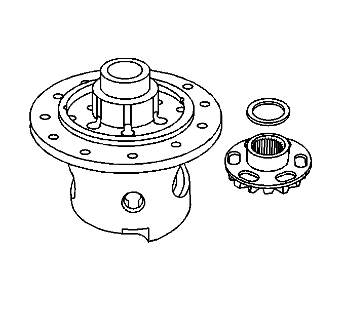
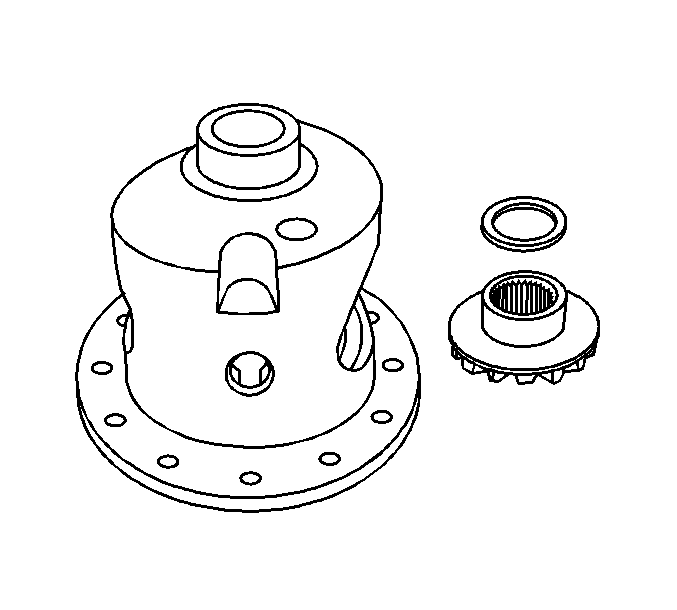
• If the same differential side gears and the thrust washers are being used, install the differential side gears and the thrust washers in their original locations. • The locking differential side gear and the differential side gear are not interchangeable. The side gears must be installed in the correct location in order for the locking differential to function properly.
- Measure the backlash of the pinion gears to differential side gear and locking differential side gear. Refer to Locking Differential Adjustment .
- Install the differential side gear thrust washer to the locking differential side gear.
- Install the locking differential side gear and thrust washer into the ring gear side of the differential case.
- Install the differential side gear thrust washer to the differential side gear.
- Install the differential side gear and thrust washer into the bell side of the differential case.
- Install the differential pinion gears and thrust washers by doing the following:
- Install the pinion shaft.
- Install a new pinion shaft lock bolt.
- Install the locking differential clutch springs.
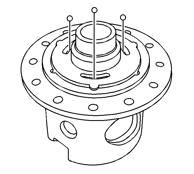
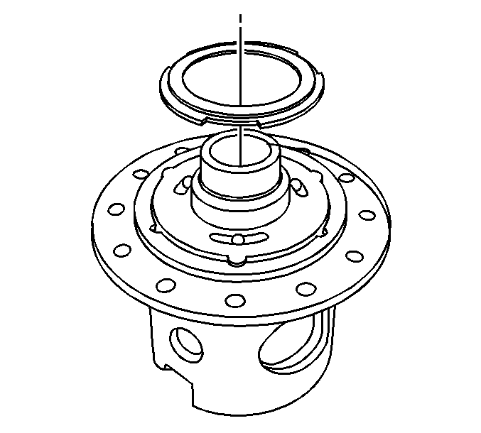
- Install the locking differential clutch spring retainer and the differential carrier lock pins.
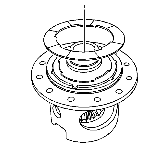
- Install the inboard locking differential ball bearing plate.
- Install the locking differential ball bearings.
- Install the outboard locking differential ball bearing plate.
- Install the locking differential coil plate.
- Install the locking differential coil assembly.
- Install the differential bearing race.
- Install the differential bearing retainer by performing the following steps:
- Install the ring gear. Refer to Drive Pinion and Ring Gear Replacement in Rear Drive Axle.
- Install the differential side bearings. Refer to Differential Side Bearings Replacement in Rear Drive Axle.
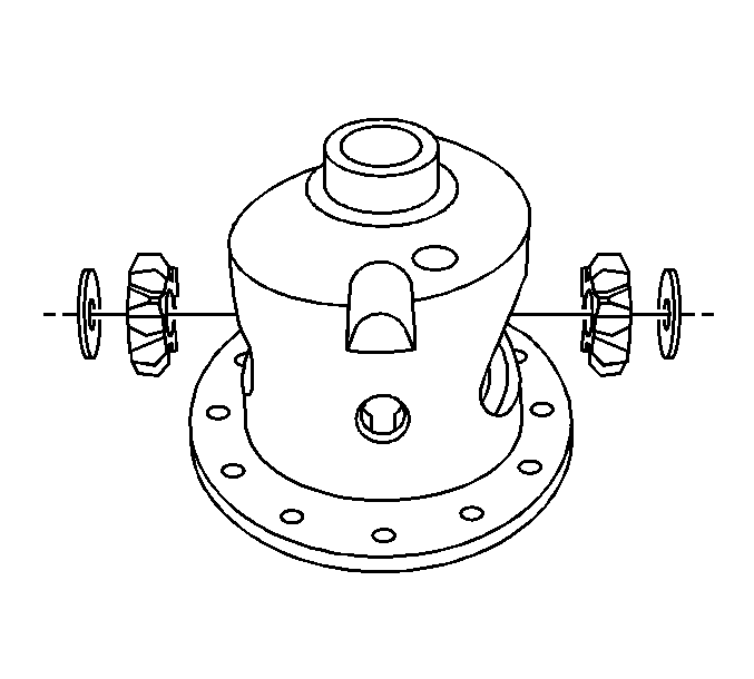
| 6.1. | Position both pinion gears and thrust washers between the differential side gears. |
Place the pinion gears and thrust washers 180 degrees across from each other.
| 6.2. | Rotate the differential side gears until both pinion gears and thrust washers are directly opposite the opening in the differential case. |
Line up the pinion shaft opening in each of the pinion gears with the pinion shaft opening in the differential case.
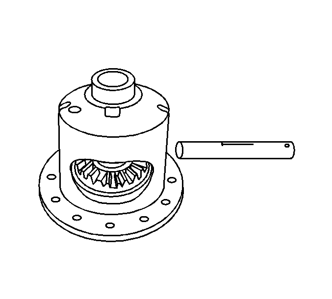
Notice: Refer to Fastener Notice in the Preface section.
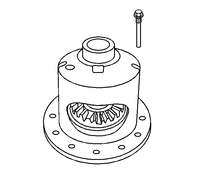
Tighten
Tighten the new pinion shaft lock bolt to 50 N·m (37 lb ft).
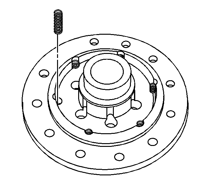
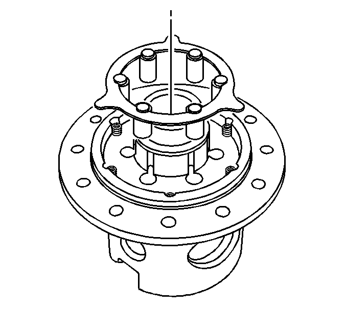
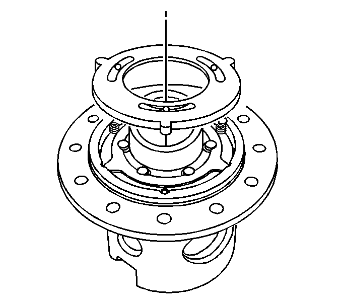
Place the inboard locking differential ball bearing plate on the three exposed differential clutch springs.
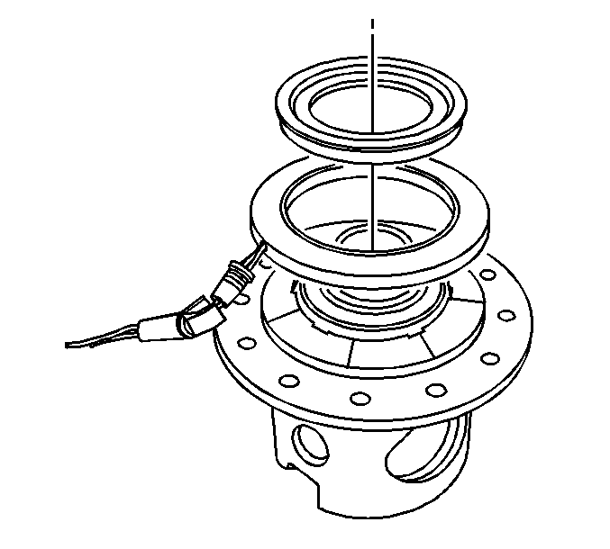
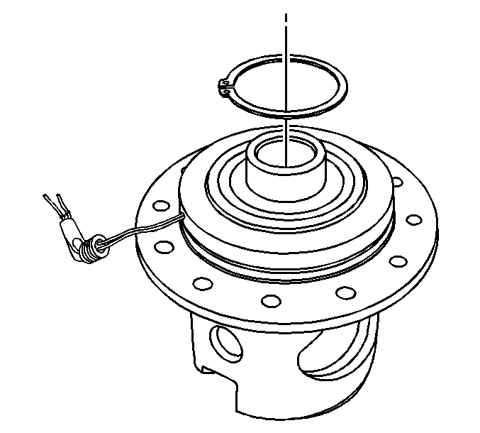
Important: The differential bearing race must be compressed in order to install the differential bearing retainer.
| 17.1. | Install the differential bearing retainer. |
| 17.2. | With the aid of an assistant, push the differential bearing race down towards the differential case in order to compress the differential bearing retainer and differential coil assembly against the locking differential coil plate. |
| 17.3. | Install the differential bearing retainer. |
Ensure the differential bearing retainer is evenly and fully seated in the differential bearing retainer slot before releasing the differential bearing race.
