For 1990-2009 cars only
Removal Procedure
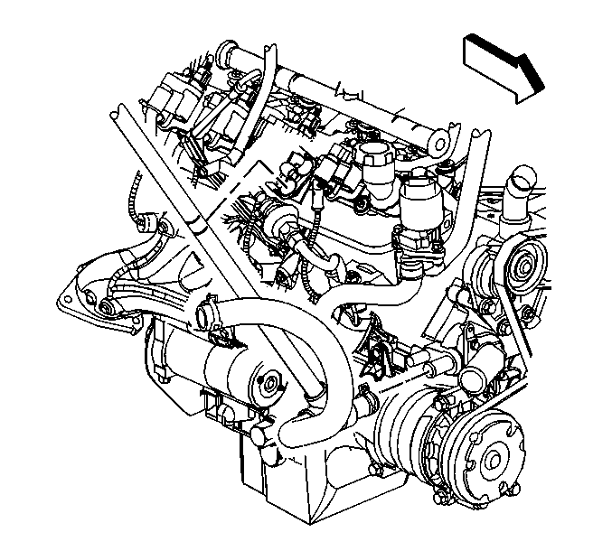
- Drain the cooling system. Refer to Cooling System Draining and Filling .
- Loosen the air cleaner outlet duct clamps at the following locations:
- Remove the radiator inlet hose clip from the outlet duct.
- Remove the air cleaner outlet duct.
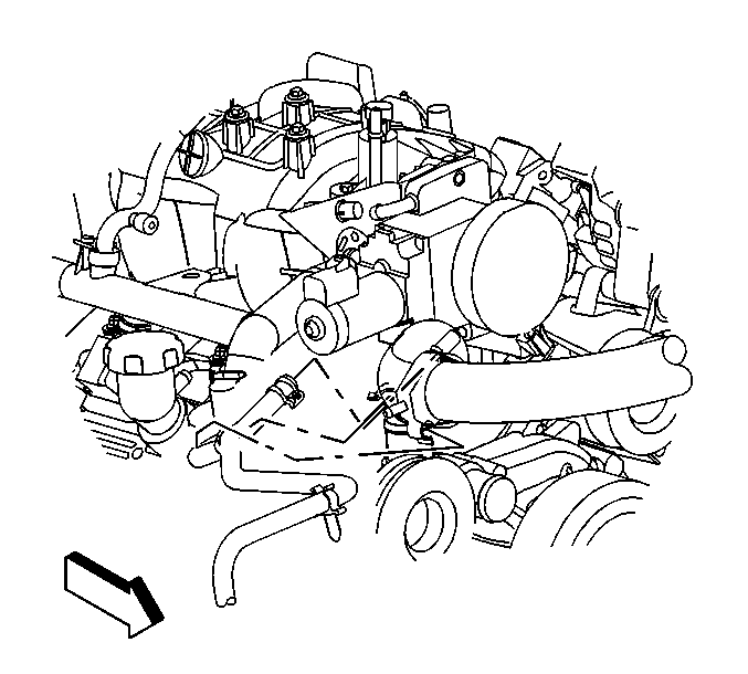
- Remove the radiator vent inlet hose from the radiator hose clips.
- Reposition the inlet hose clamp at the water pump.
- Remove the inlet hose from the water pump.
- Remove the fan blade. Refer to Fan Replacement .
- Remove the accessory drive belt. Refer to Drive Belt Replacement - Accessory .
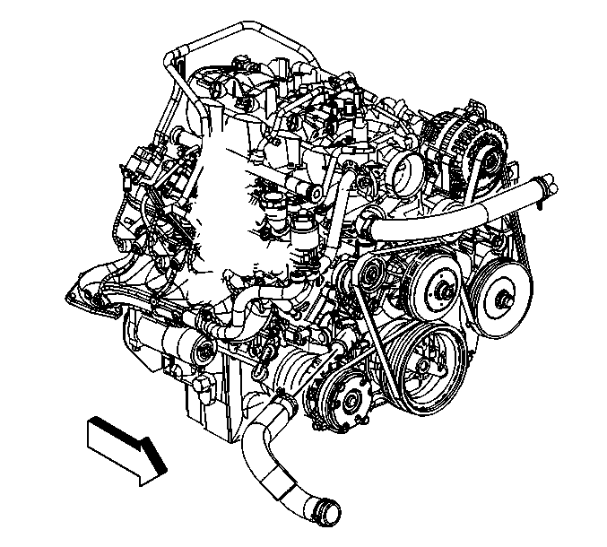
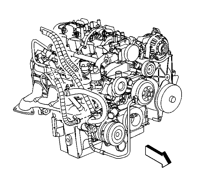
- Reposition the outlet hose clamp at the water pump.
- Remove the outlet hose from the water pump.
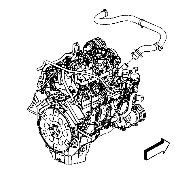
- Reposition the surge tank outlet hose clamp at the water pump.
- Remove the surge tank outlet hose from the water pump.
- Reposition the heater inlet hose clamp at the water pump.
- Remove the heater inlet hose from the water pump.
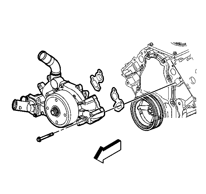
- Remove the water pump bolts.
- Remove the water pump and gaskets.
- Discard the water pump gaskets.
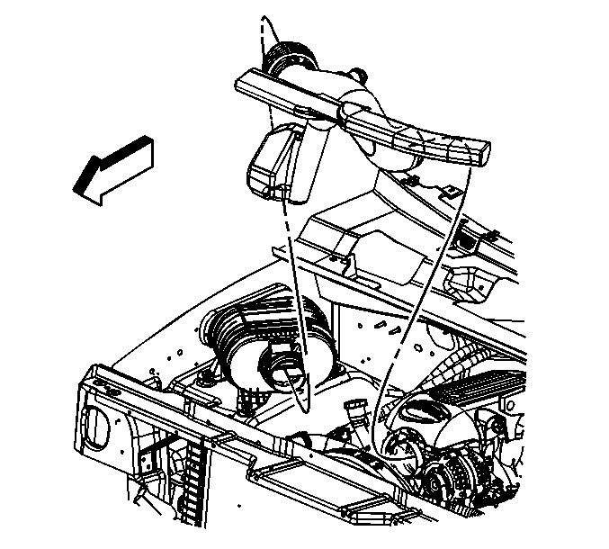
| • | Throttle body |
| • | Mass airflow (MAF) intake air temperature (IAT) sensor |
Installation Procedure
Important: All gaskets surfaces are to be free of oil or other foreign material during assembly.
- Install the water pump and NEW gaskets.
- Install the water pump bolts.
- Tighten the water pump bolts a first pass to 15 N·m (11 lb ft).
- Tighten the water pump bolts a final pass to 30 N·m (22 lb ft).
- Install the heater inlet hose to the water pump.
- Position the heater inlet hose clamp at the water pump.
- Install the surge tank outlet hose to the water pump.
- Position the surge tank outlet hose clamp at the water pump.
- Install the outlet hose to the water pump.
- Position the outlet hose clamp at the water pump.
- Install the accessory drive belt. Refer to Drive Belt Replacement - Accessory .
- Install the fan blade. Refer to Fan Replacement .
- Install the inlet hose to the water pump.
- Position the inlet hose clamp at the water pump.
- Install the engine vent inlet hose to the radiator hose clips.
- Install the air cleaner outlet duct.
- Install the radiator inlet hose clip to the outlet duct.
- Tighten the air cleaner outlet duct clamps at the following locations:
- Fill the cooling system. Refer to Cooling System Draining and Filling .
Notice: Refer to Fastener Notice in the Preface section.

Tighten


Important: Align the arrow at the throttle body end of the duct with the throttle body attaching stud.
| • | Throttle body |
| • | MAF/IAT sensor |
Tighten
Tighten the air cleaner outlet duct clamp screws to 7 N·m (62 lb in).
