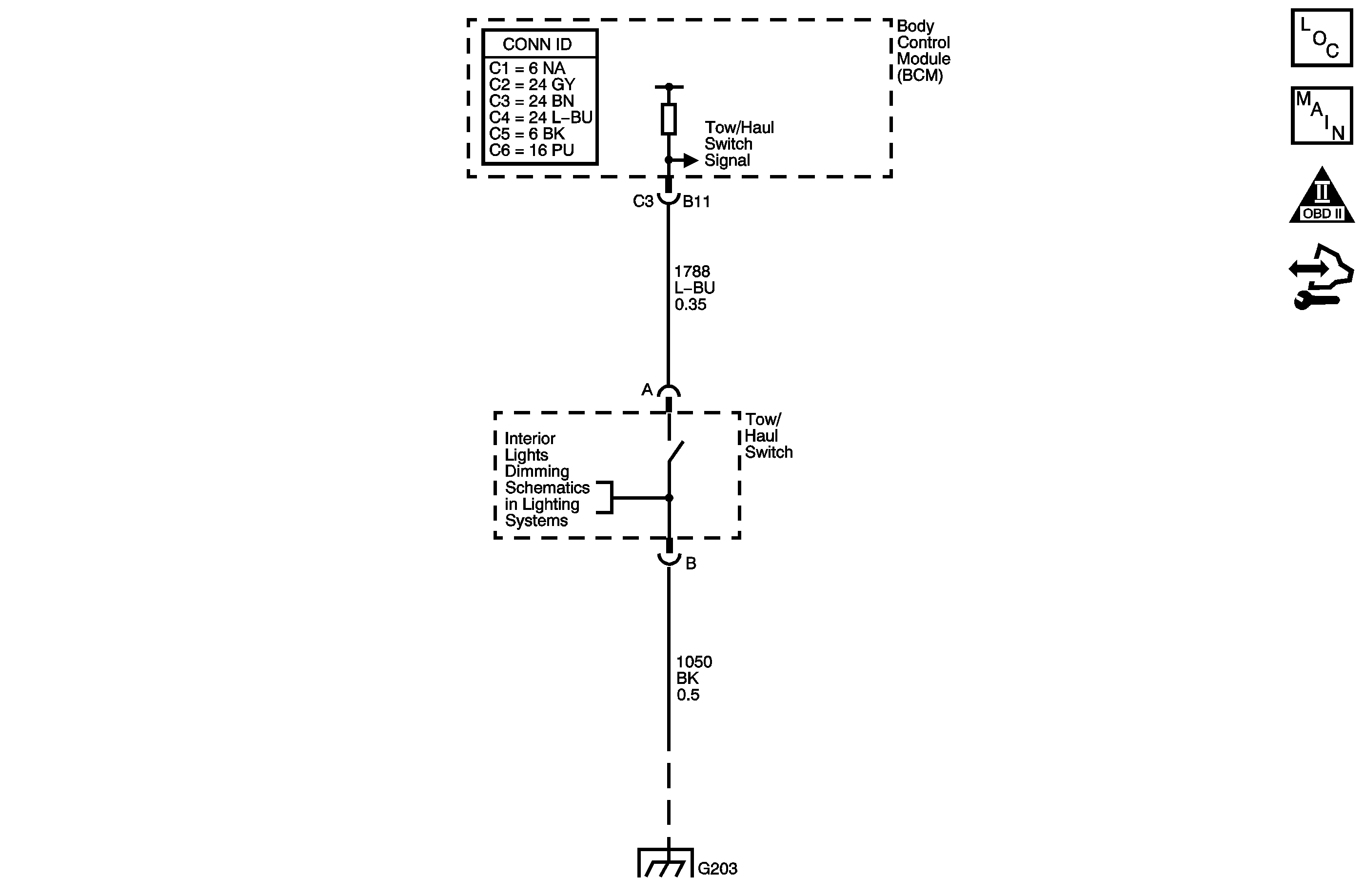
Circuit Description
Tow/haul mode enables the operator to achieve enhanced shift performance when towing or hauling a load. When tow/haul mode is selected, the tow/haul switch input signal to the body control module (BCM) is momentarily toggled to zero volts. This signals the powertrain control module (PCM) to extend the length of time between upshifts and increase transmission line pressure. Cycling the tow/haul switch again disables tow/haul mode and returns the transmission to a normal shift pattern.
Diagnostic Aids
If the electrical circuit tests are OK and the tow/haul shift pattern is not occurring, there may be a mechanical/hydraulic condition that prevents tow/haul operation. Refer to Symptoms - Automatic Transmission .
Test Description
The numbers below refer to the step numbers on the diagnostic table.
-
This step tests for a faulty tow/haul switch.
-
This step tests for voltage input from the BCM to the tow/haul switch.
-
This step tests for voltage through the body wiring harness.
-
This step tests for ground integrity at the splice pack.
Step | Action | Values | Yes | No |
|---|---|---|---|---|
1 |
Does the scan tool display Active when the switch is first pressed, and then Inactive when the switch is pressed again? | -- | Go to Testing for Intermittent Conditions and Poor Connections | Go to Step 2 |
Does the scan tool Tow/Haul Mode indicate a status change? | -- | Go to Step 7 | Go to Step 3 | |
Using the DMM and the J 35616 GM Terminal Test Kit, measure the voltage at the tow/haul switch signal circuit of the I/P wiring harness connector. Is ignition voltage measured? | -- | Go to Step 6 | Go to Step 4 | |
4 | Using the DMM and the J 35616 , measure the voltage at the tow/haul switch signal circuit of the body control module (BCM). Does the voltage measure near the specified value? | 10-12 V | Go to Step 5 | Go to Step 8 |
5 | Test the signal circuit of the tow/haul switch for an open or shorted condition. Refer to Circuit Testing and Wiring Repairs . Did you find and correct the condition? | -- | Go to Step 9 | Go to Testing for Intermittent Conditions and Poor Connections |
Test the ground circuit of the tow/haul switch for an open or high resistance condition between the I/P wiring harness connector and ground. Refer to Circuit Testing and Wiring Repairs . Did you find and correct the condition? | -- | Go to Step 9 | Go to Testing for Intermittent Conditions and Poor Connections | |
Replace the tow/haul switch. Refer to Tow/Haul Switch Replacement . Did you complete the replacement? | -- | Go to Step 9 | -- | |
8 | Replace the BCM. Refer to Control Module References for replacement, setup and programming. Did you find and correct the condition? | -- | Go to Step 9 | -- |
9 | After the repair is complete, observe Tow/Haul Mode parameter on the scan tool display, while cycling the tow/haul switch. Does the scan tool display Active when the switch is first pressed, and then Inactive when the switch is pressed again? | -- | System OK | Go to Step 1 |
