For 1990-2009 cars only
Special Tools
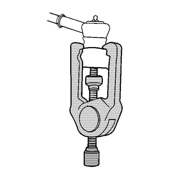
J 24319-B Steering Linkage and Tie Rod Puller
Removal Procedure
- Remove the front tire and wheel assembly. Refer to Tire and Wheel Removal and Installation.
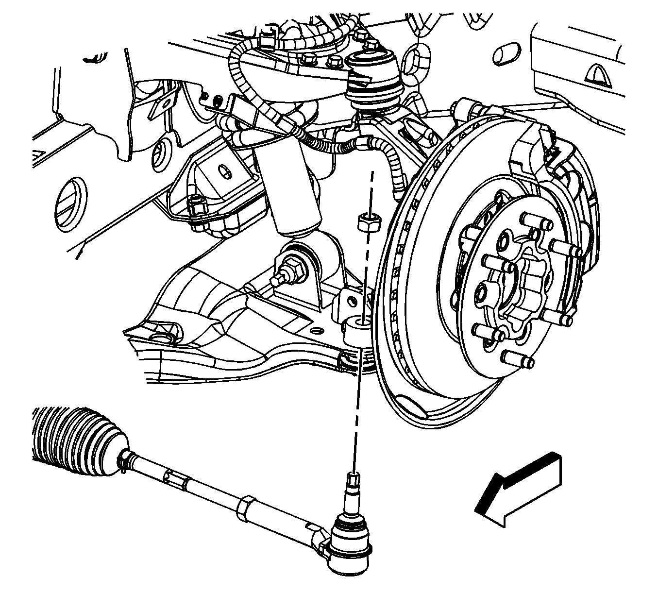
- Remove and discard the rack and pinion outer tie rod end nut.
- Disconnect the rack and pinion outer tie rod end from the steering knuckle using puller J 24319-B .
- Loosen the rack and pinion inner tie rod nut and remove the rack and pinion outer tie rod end.
- Discard the rack and pinion inner tie rod nut.
- Clean the tapered surface of the steering knuckle.


Caution: Do not attempt to disconnect a steering linkage joint by driving a wedge between the joint and the attached part. Seal damage may result which will cause premature failure of the joint.
Note: Mark the location of the rack and pinion inner tie rod nut.
Installation Procedure
- Lubricate the rack and pinion inner tie rod threads with a suitable chassis lubricant.
- Install a new rack and pinion inner tie rod nut in the same position as the old one.
- Install the rack and pinion outer tie rod end to the rack and pinion inner tie rod.
- Install the rack and pinion outer tie rod end to the steering knuckle.
- Install the new rack and pinion outer tie rod end nut.
- Tighten the rack and pinion inner tie rod nut against the rack and pinion outer tie rod end.
- Install the front tire and wheel assembly. Refer to Tire and Wheel Removal and Installation.
- Adjust the front toe. Refer to Front Toe Adjustment.

Caution: Refer to Fastener Caution in the Preface section.
Tighten
Tighten the nut to 71 N·m (52 lb ft).
