For 1990-2009 cars only
Special Tools
| • | J 6125-1B Slide Hammer with Adapter |
| • | J 41818 Crankshaft Bearing Cap Remover |
- Remove the engine assembly. Refer to Engine Replacement .
- Remove both cylinder head assemblies.
- Remove the oil pan assembly.
- Remove the piston and connecting rod assemblies. Refer to Piston, Connecting Rod, and Bearing Removal .
- Remove the oil pump assembly.
- Remove the crankshaft rear oil seal and plate assembly.
- Remove the crankshaft position sensor.
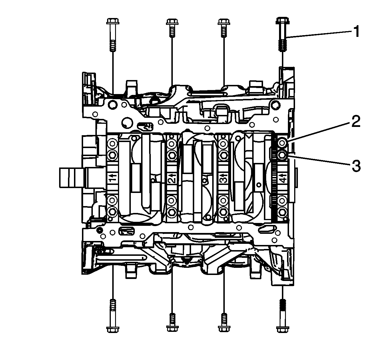
- Remove the crankshaft bearing cap side bolts (3).
- Remove the crankshaft bearing cap outer bolts (1).
- Remove the crankshaft bearing cap inner bolts (2).
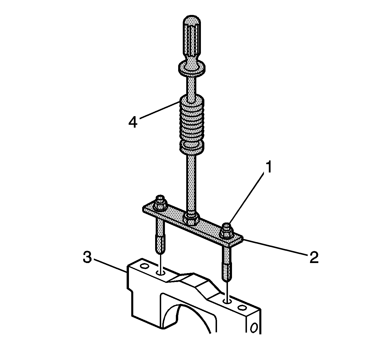
- Loosen the nuts (1) of the J 41818 (2) to separate the chambered collets.
- Install the collets into the inner bolt holes of the front main bearing cap (3).
- Install J 6125-B (4) onto the crankshaft bearing cap remover and remove the crankshaft bearing cap.
- Repeat steps 9 to 13 for the remaining crankshaft bearing caps.
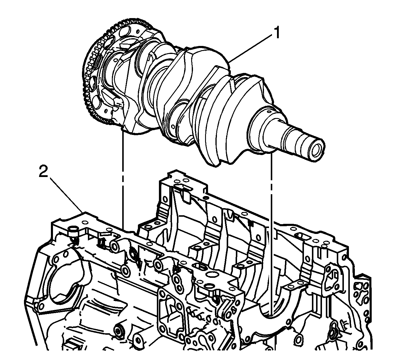
- Remove the crankshaft (1) from the engine block (2), lifting evenly to avoid jamming against the main thrust bearing.
- Place the crankshaft in a secure place.
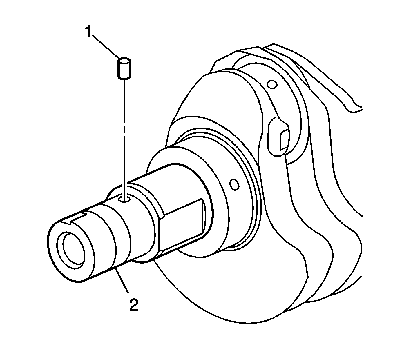
- If required, remove the crankshaft sprocket drive pin (1) from the crankshaft (2).

Important: The crankshaft bearing cap outer bolts are yield tightened during assembly and must be replaced prior to reassembly. Crankshaft bearing cap outer bolts that are not replaced will not torque to the correct clamp load and can lead to serious engine damage.

Notice: Refer to Fastener Notice in the Preface section.
Tighten
Tighten the remover nuts to 11 N·m (97 lb in).


