For 1990-2009 cars only
Special Tools
| • | DW-110-060 Engine Assembly Support Fixture |
| • | KM-470-B Angular Torque Gauge |
Removal Procedure
- Remove the fuel pump fuse.
- Start the engine. After it stalls, crank the engine for 10 seconds to rid the fuel system of fuel pressure.
- Disconnect the negative battery cable.
- Drain the engine coolant. Refer to Cooling System Draining and Filling.
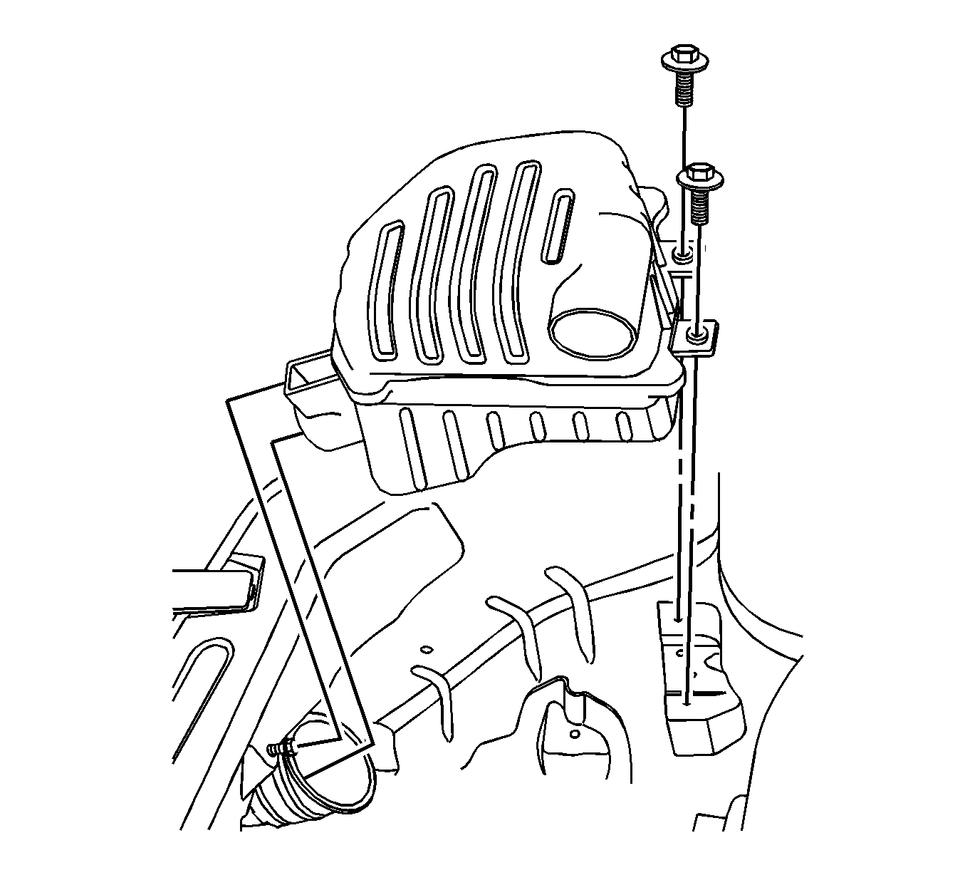
- Remove the air cleaner assembly. Refer to Air Cleaner Assembly Replacement.
- Remove the engine beautification cover and the engine beautification cover bracket.
- Disconnect the breather hose and PCV hose from the cylinder head cover.
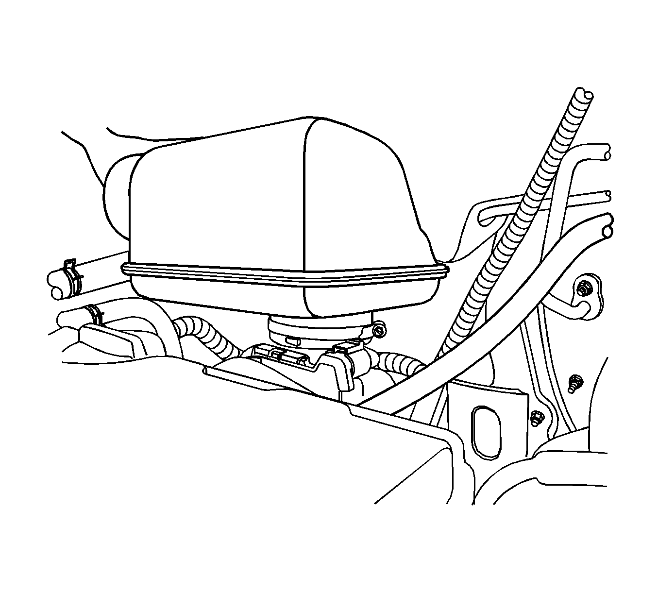
- Loosen the clamp and remove the resonator from the electronic throttle body.
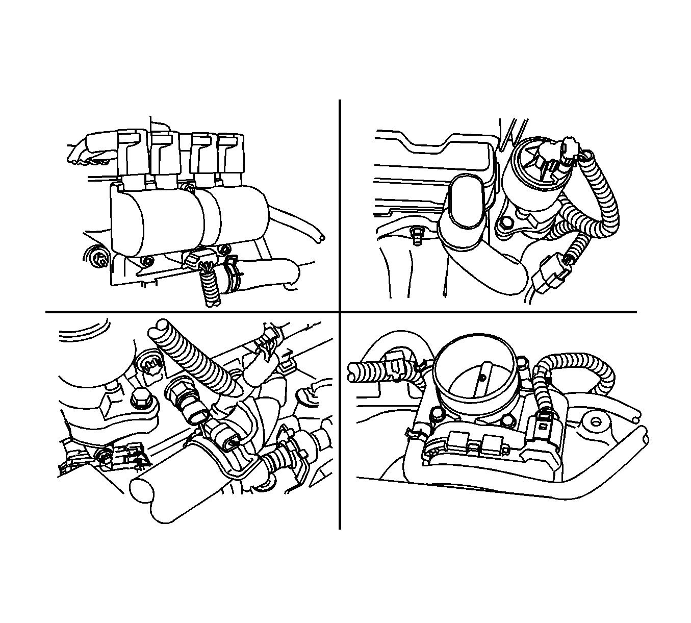
- Disconnect the direct ignition system (DIS) connector.
- Disconnect the front heated oxygen sensor connector.
- Disconnect the electronic throttle control (ETC) connector.
- Disconnect the coolant temperature sensor (CTS) connector.
- Disconnect the exhaust gas recirculation (EGR) valve connector.
- Remove the right front wheel. Refer to Tire and Wheel Removal and Installation.
- Remove the engine front shield at the position of the right front wheel.
- Remove the serpentine accessory drive belt. Refer to Drive Belt Replacement.
- Install the DW-110-060 engine assembly support fixture DW-110-060 .
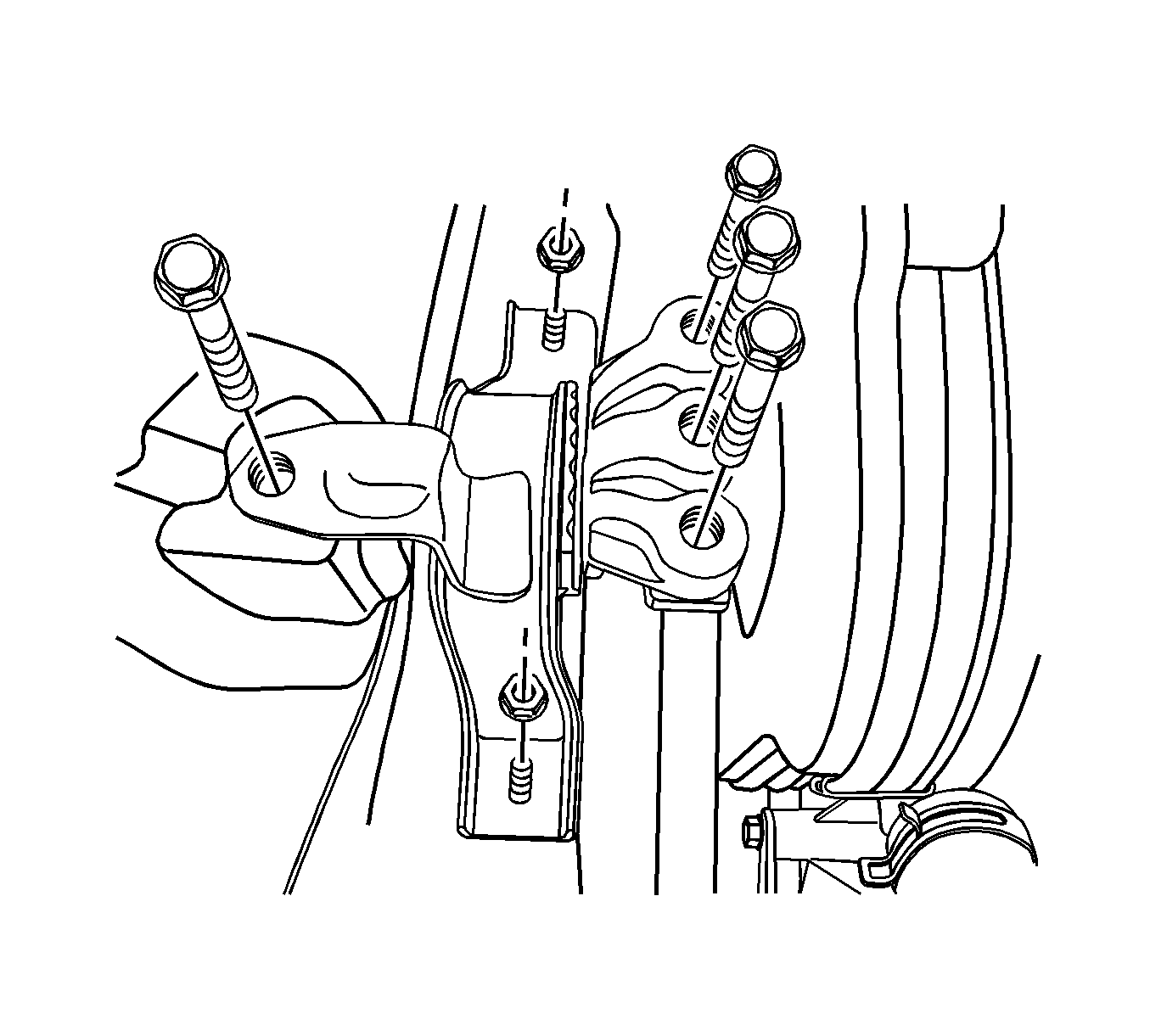
- Remove the engine mount assembly. Refer to Engine Front Mount Replacement.
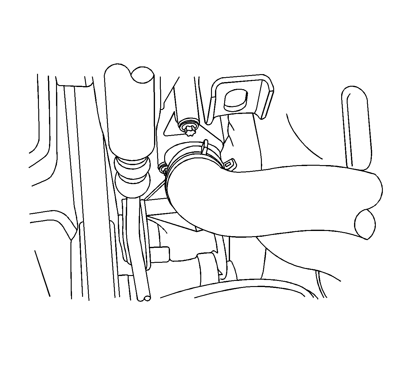
- Disconnect the upper radiator hose from the thermostat housing.
- Remove the crankshaft pulley bolts.
- Remove the crankshaft pulley.
- Remove the front timing belt cover bolts.
- Remove the front timing belt cover.
- Remove the timing belt. Refer to Timing Belt Replacement.
- Remove the camshaft cover and the gasket. Refer to Camshaft Cover Replacement.
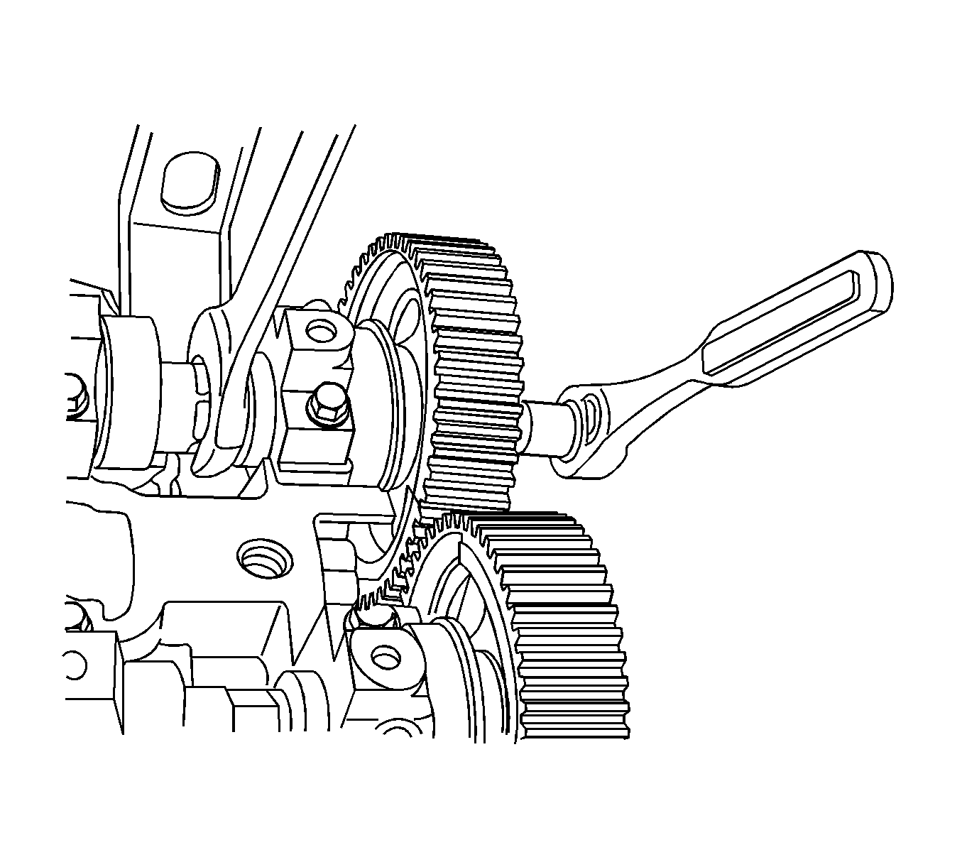
- While holding the intake camshaft firmly in place, remove the intake camshaft gear bolts.
- Remove the intake camshaft gear.
- While holding the exhaust camshaft firmly in place, remove the exhaust camshaft gear bolts.
- Remove the exhaust camshaft gear.
- Remove the timing belt automatic tensioner bolts.
- Remove the timing belt automatic tensioner.
- Remove the timing belt idler pulley bolt and nut.
- Remove the timing belt idler pulley.
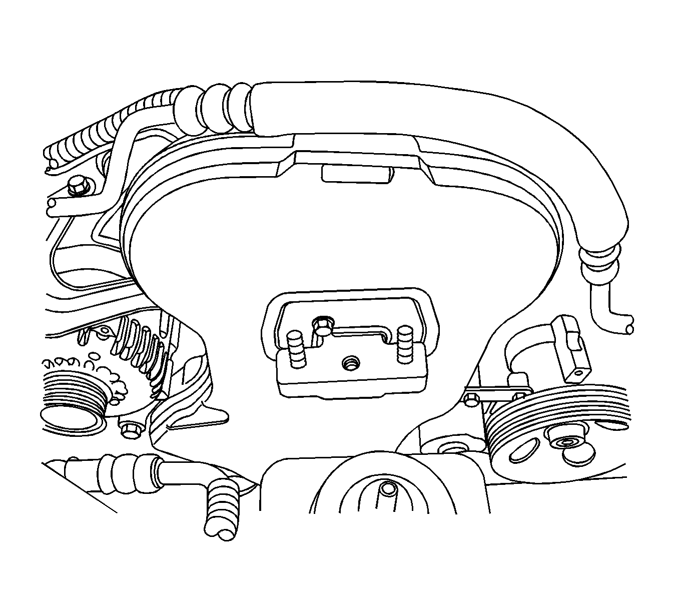
- Remove the engine mount adapter support bracket bolts.
- Remove the engine mount adapter support bracket.
- Remove the crankshaft gear.
- Remove the camshaft position (CMP) sensor.
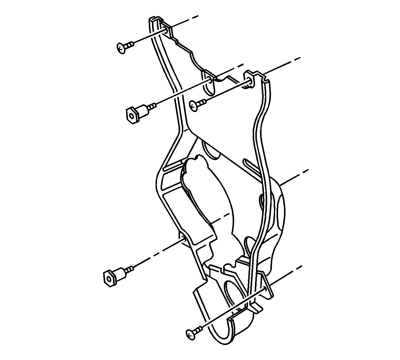
- Remove the rear timing belt cover bolts.
- Remove the rear timing belt cover.
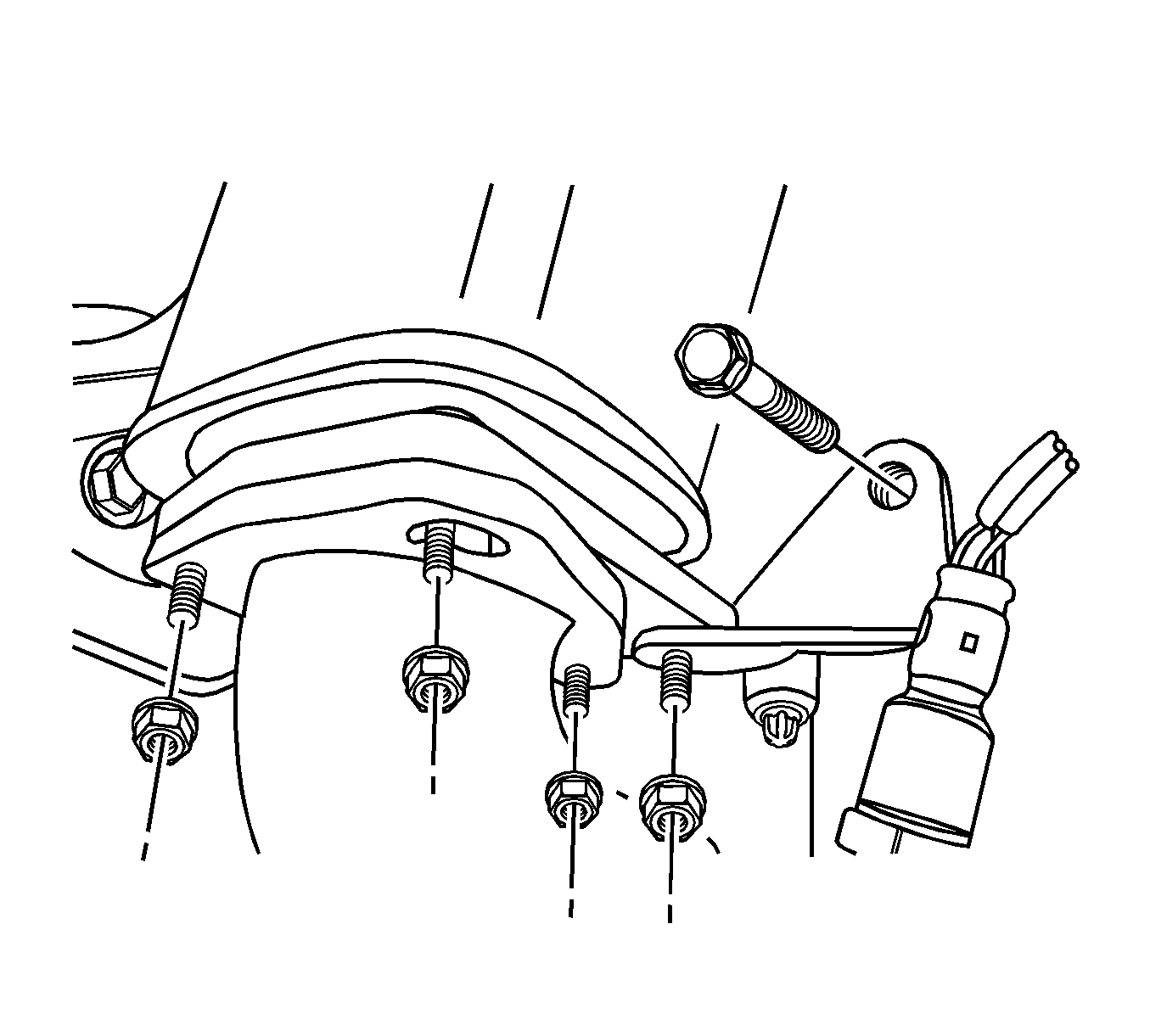
- Remove the pup converter-to-exhaust front pipe retaining nuts.
- Remove the exhaust front pipe mounting bracket bolt and nut.
- Remove the exhaust front pipe from the pup converter. Refer to Front Pipe Replacement.
- Disconnect all of the necessary vacuum hoses.
- Remove the intake manifold support bracket bolts and the bracket.
- Remove the ground terminal retaining bolt from the intake manifold.
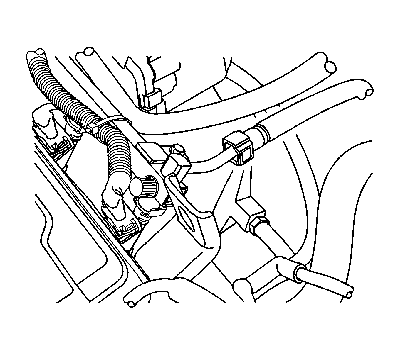
- Disconnect the fuel feed line at the fuel rail.
- Disconnect the coolant hoses at the rear cylinder head and the exhaust gas recirculation (EGR) valve adapter.
- Disconnect the coolant hoses from the electronic throttle body.
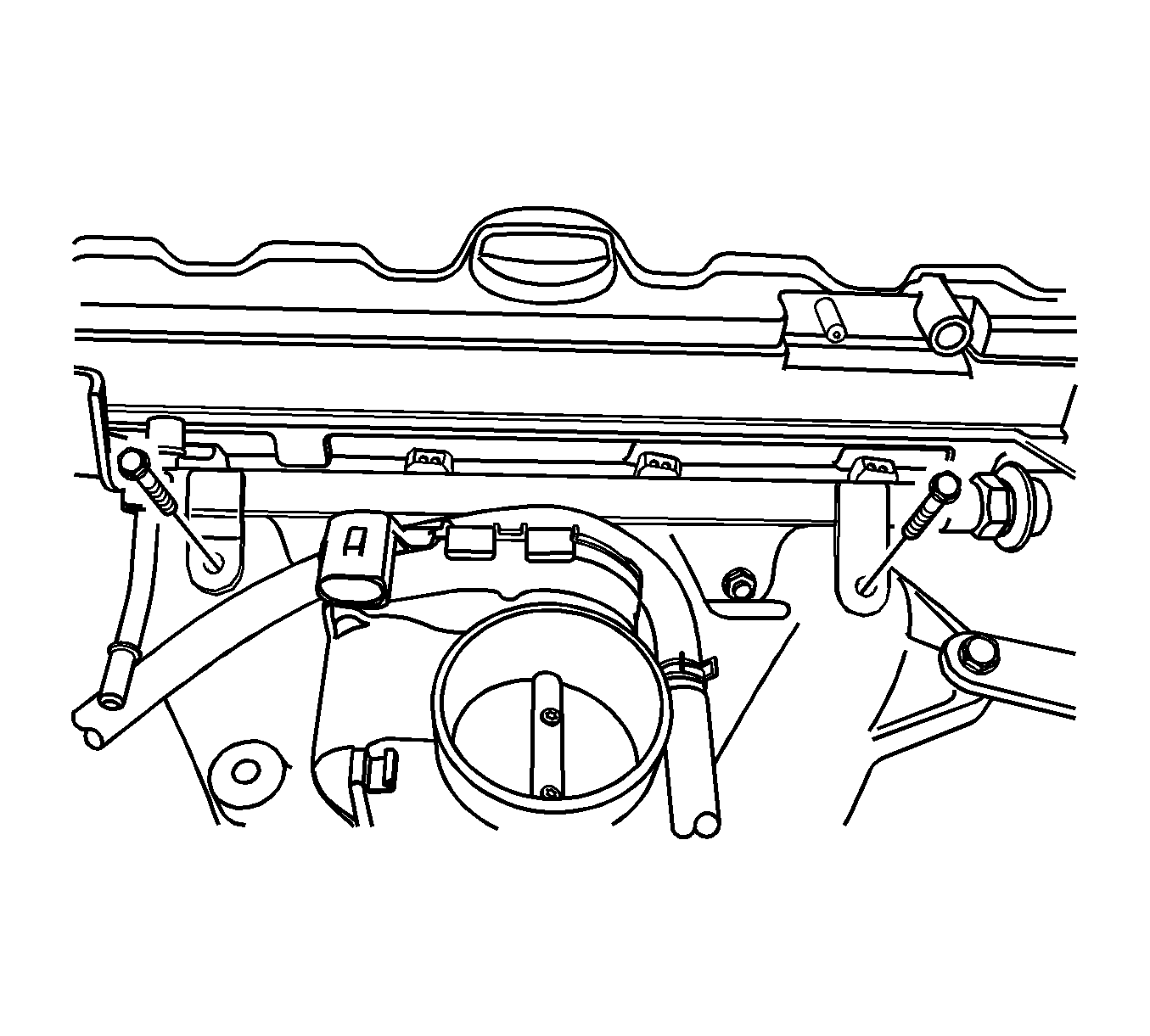
- Remove the fuel rail assembly. Refer to Fuel Injection Fuel Rail Assembly Replacement.
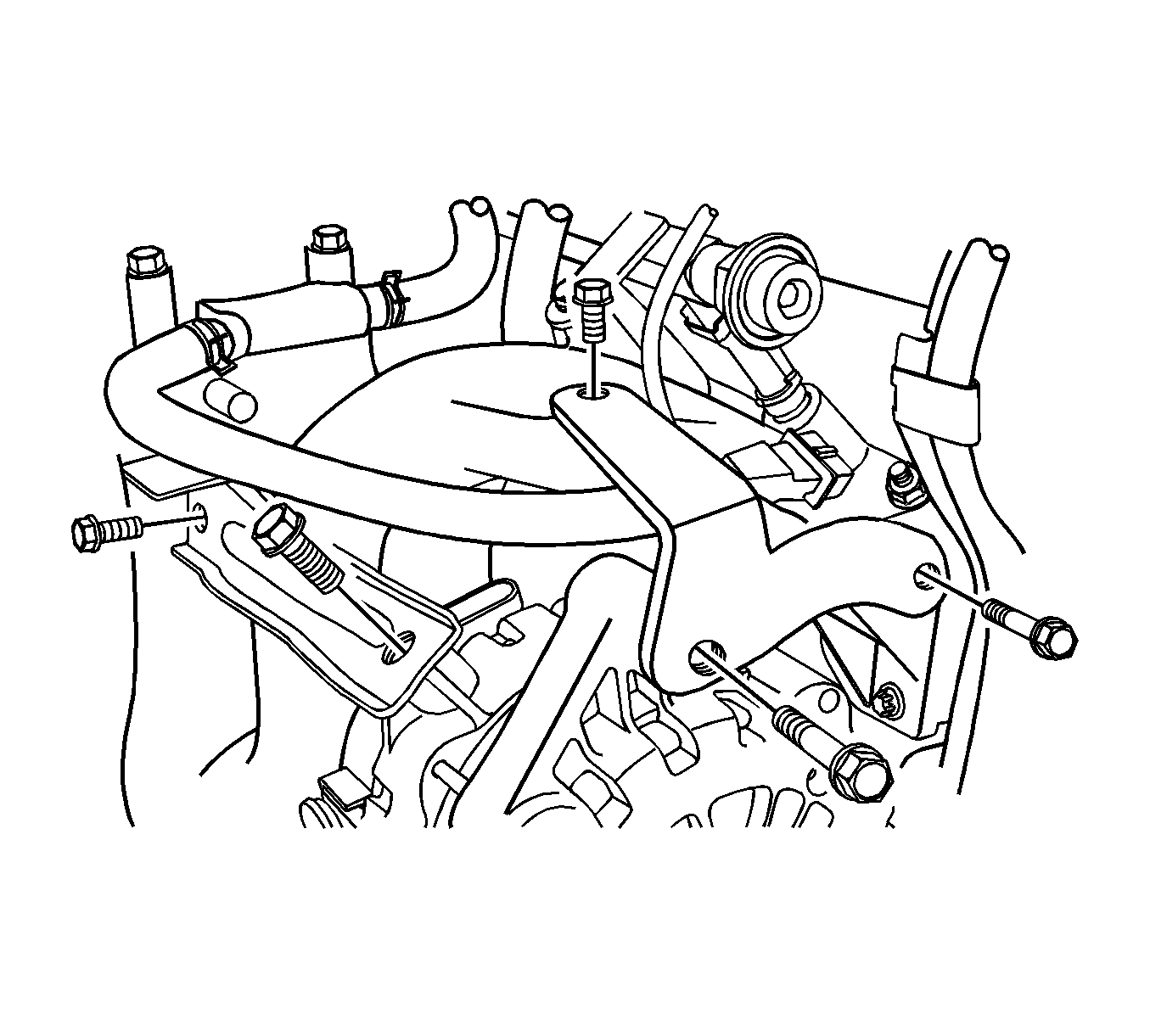
- Remove the generator upper bracket bolts.
- Remove the generator upper bracket.
- Remove the generator-to-intake manifold strap bracket bolts on the generator and the intake manifold.
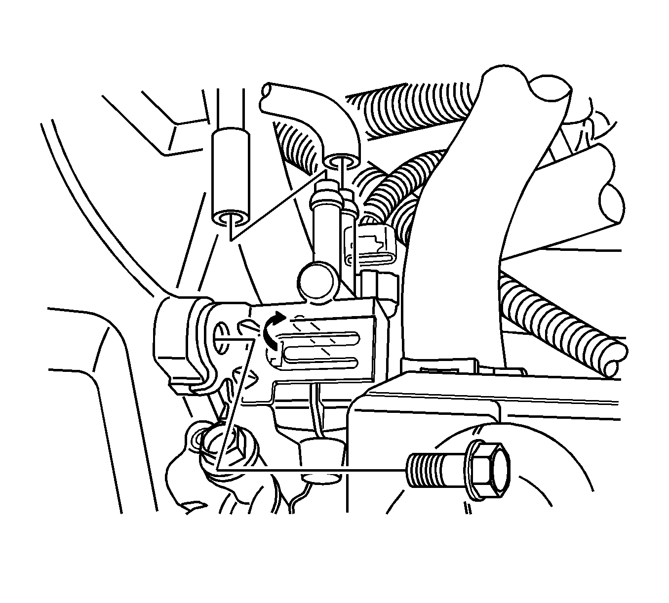
- Remove the evaporative (EVAP) emission canister purge solenoid valve bracket bolt.
- Remove the EVAP emission canister purge solenoid valve.
- Remove the camshaft. Refer to Camshaft Replacement.
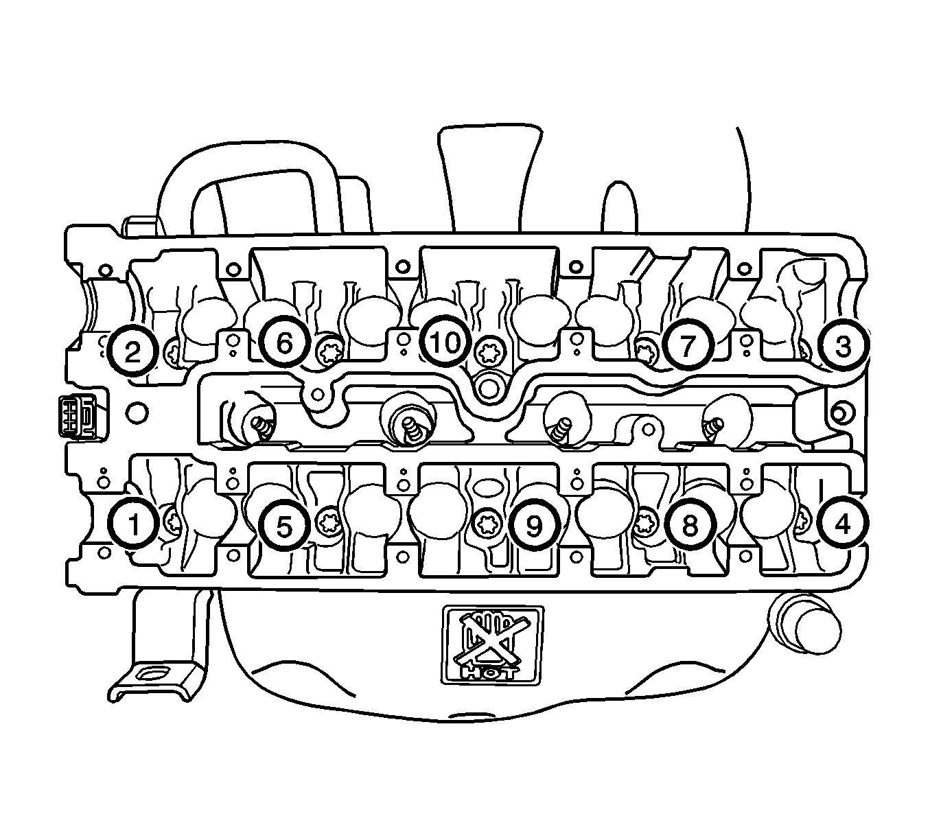
- Loosen all of the cylinder head bolts gradually in the sequence shown.
- Remove the cylinder head bolts.
- Remove the cylinder head with the intake manifold and the exhaust manifold attached.
- Remove the cylinder head gasket.
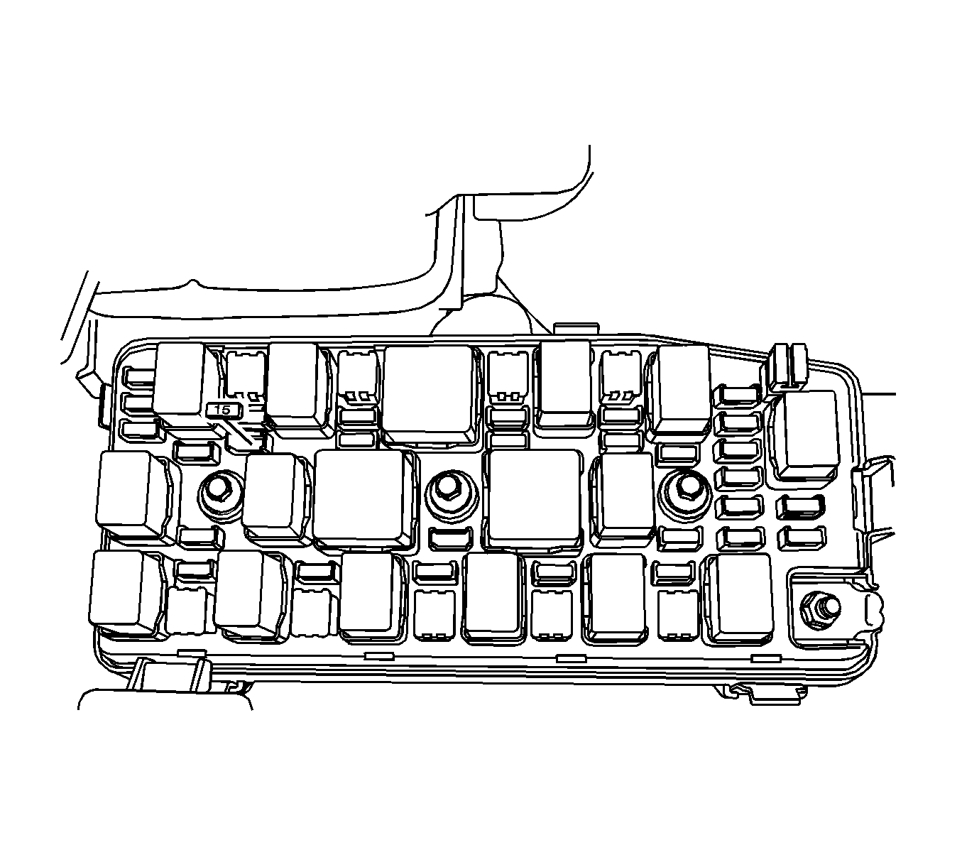
Warning: Refer to Battery Disconnect Warning in the Preface section.
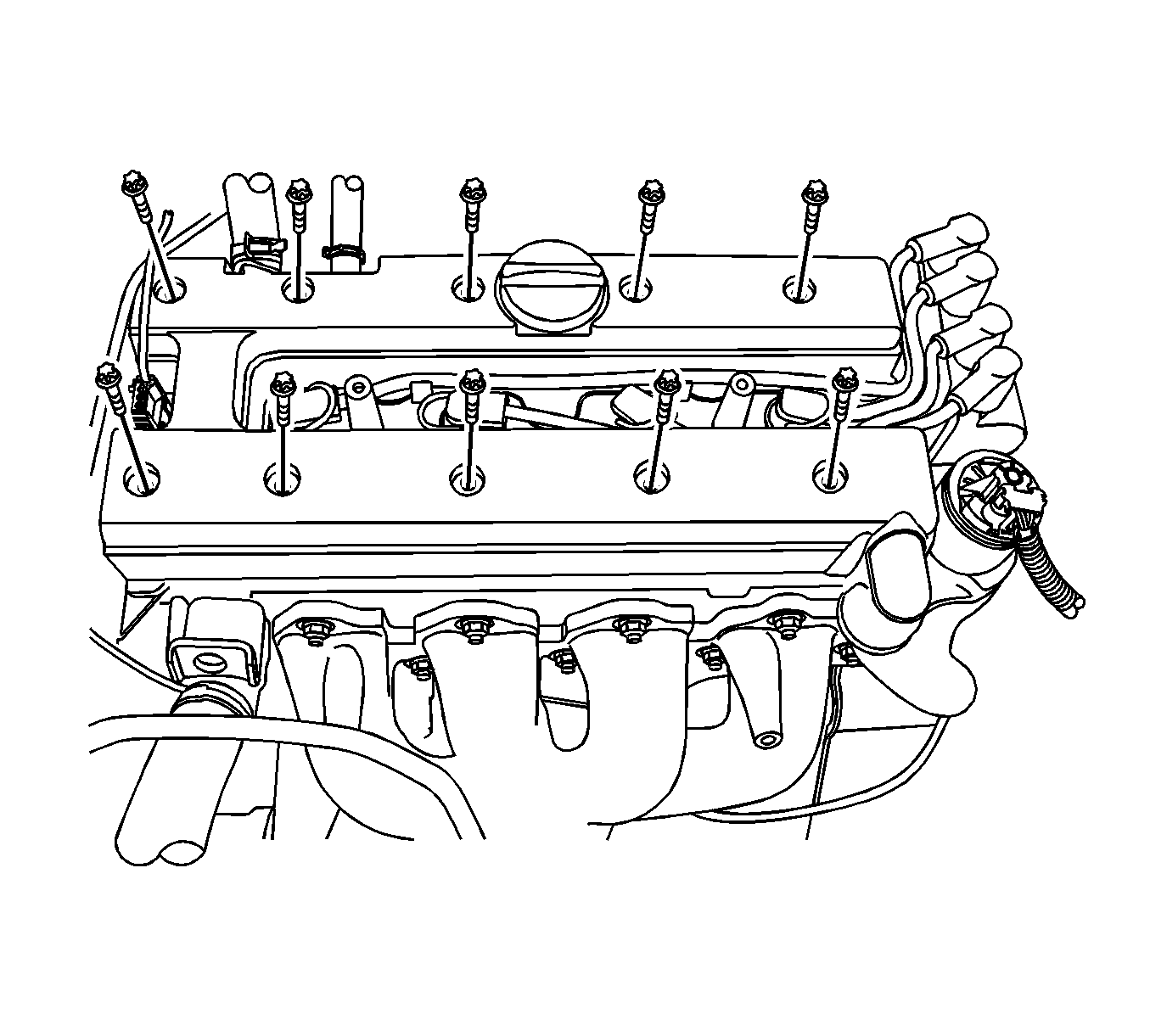

Note: Handle the camshafts carefully to prevent nicks or scratches.
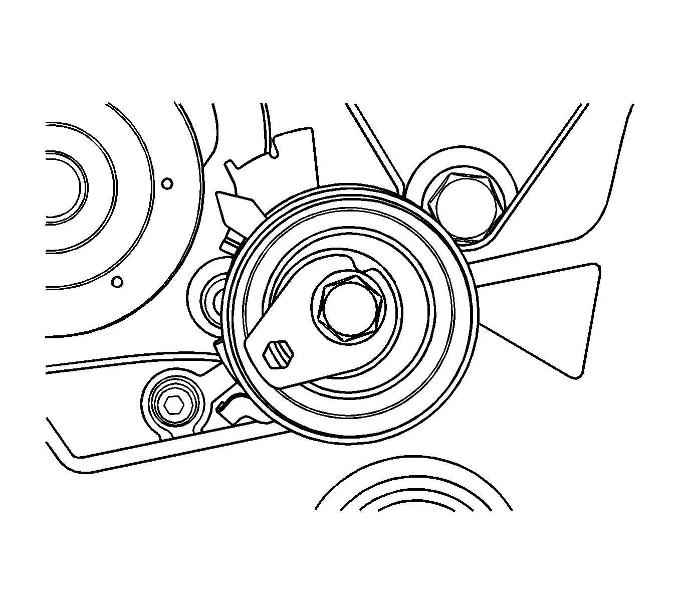
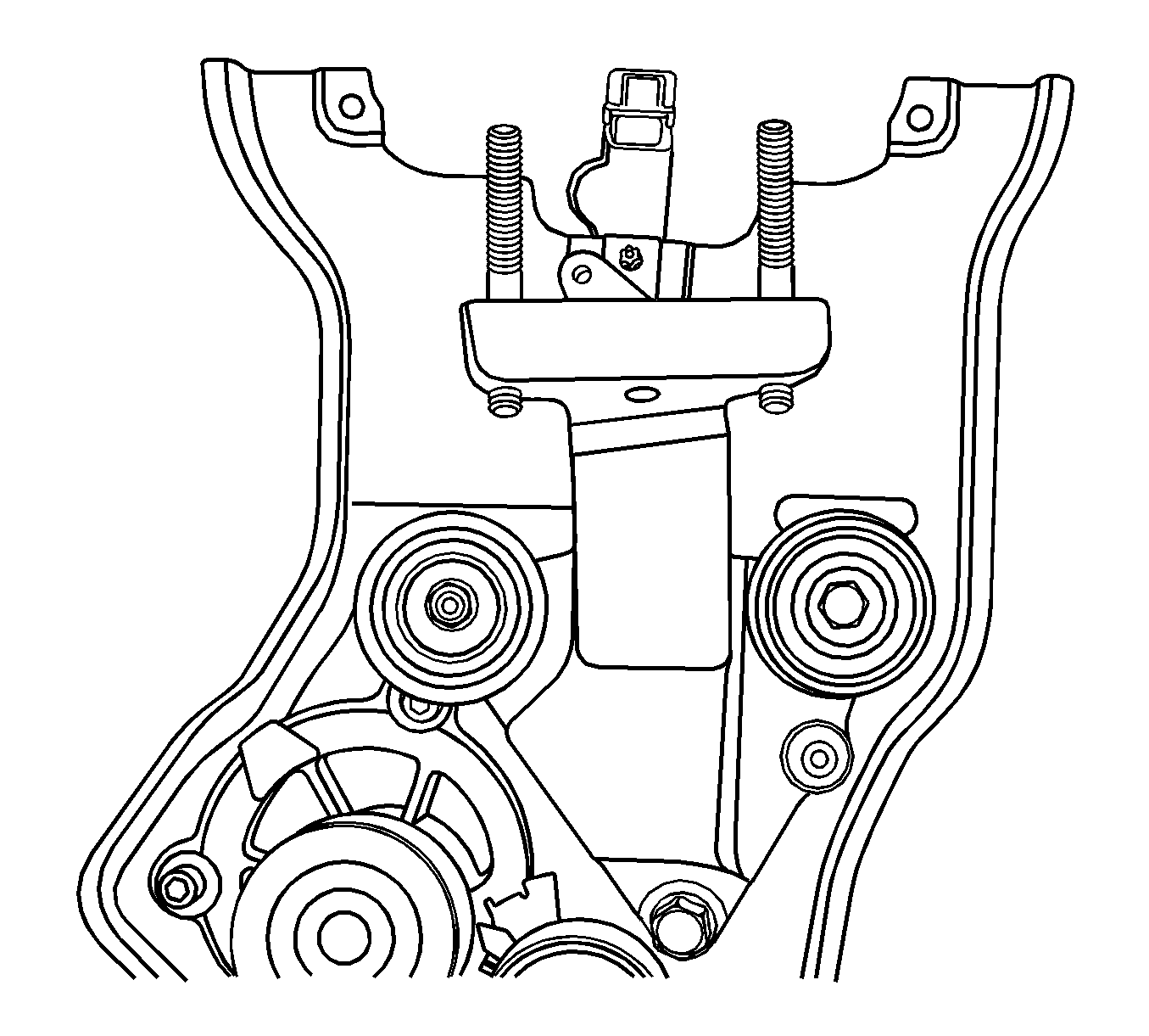
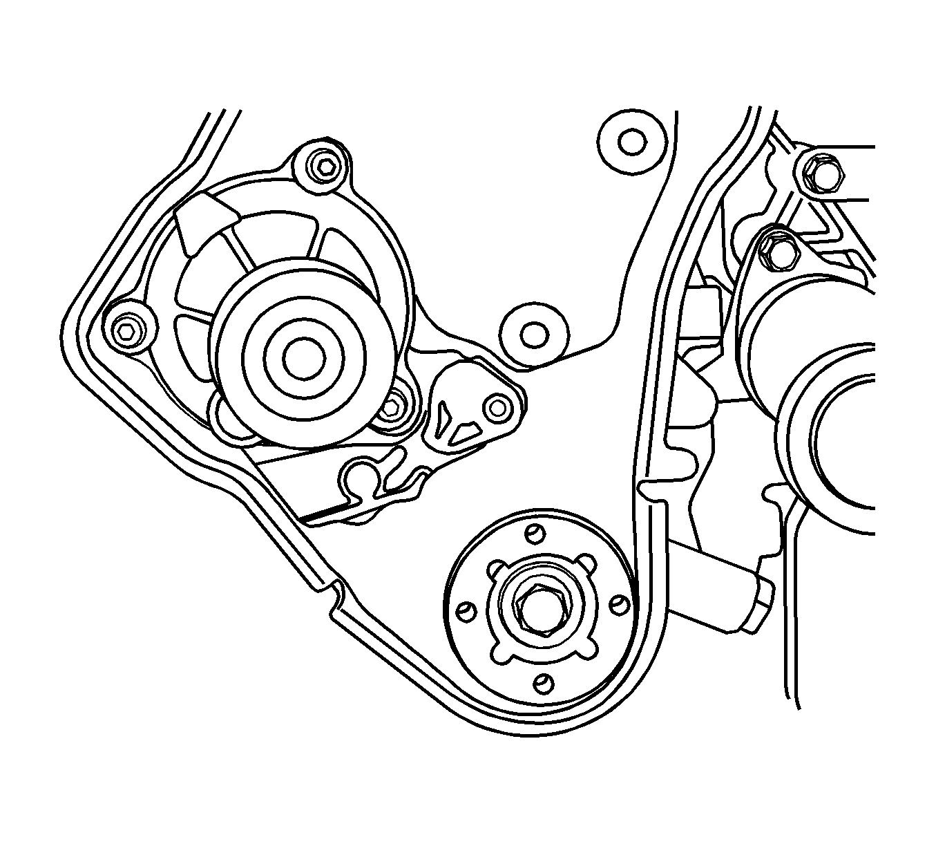
Note: Prevent any engine oil or coolant from entering the cylinders when removing the cylinder head.
Cleaning Procedure
- Clean the gasket surfaces of the cylinder head and the engine block.
- Make sure the gasket surfaces of the cylinder head and the engine block are free of nicks and heavy scratches.
- Clean the cylinder head bolts.
- Inspect the cylinder head for warpage. Refer to Cylinder Head Cleaning and Inspection.
Installation Procedure
- Install the new cylinder head gasket.
- Install the cylinder head with the intake manifold and the exhaust manifold attached.
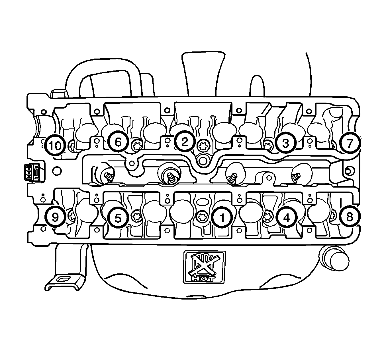
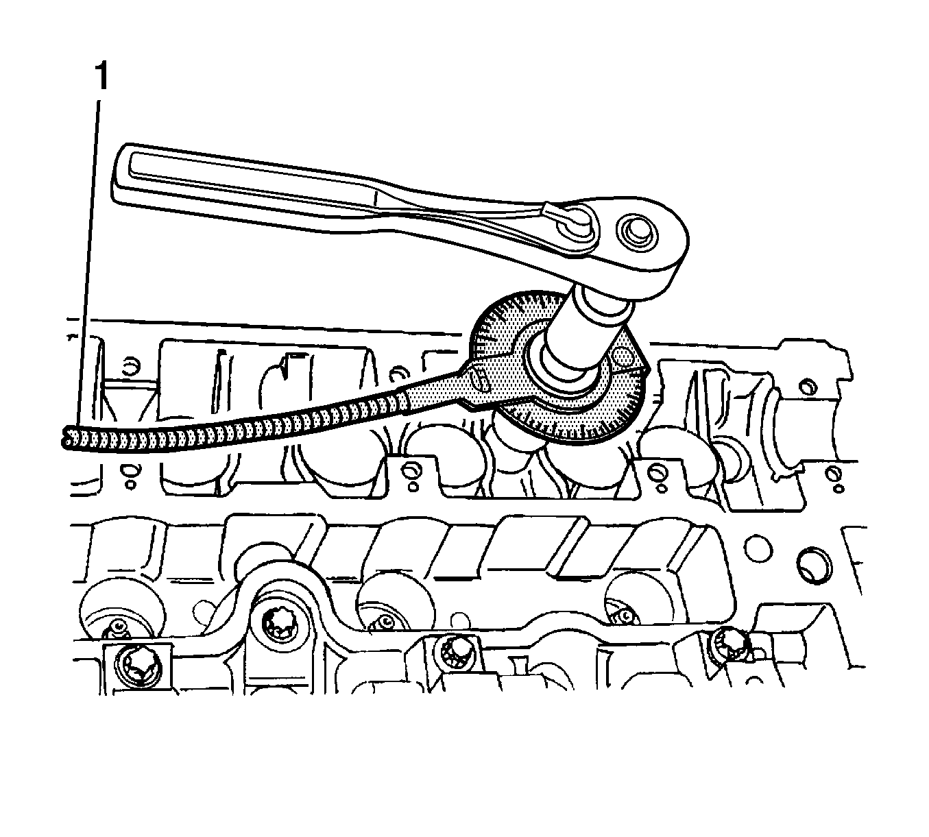
- Install the cylinder head bolts and tighten the cylinder head bolts gradually in the sequence shown. Tighten to 25 N·m (18 lb ft) and turn the bolts another 3 turns of 90 degrees using KM-470-B angular torque gauge .
- Install the camshaft. Refer to Camshaft Replacement.
- Install the EVAP emission canister purge solenoid valve and tighten the bracket bolt to 5 N·m (44 lb in).
- Install the generator upper bracket and tighten:
- Install the generator-to-intake manifold strap bracket and tighten:
- Connect the coolant hoses to the electronic throttle body, rear cylinder head and the EGR valve bracket.
- Install the fuel rail assembly. Refer to Fuel Injection Fuel Rail Assembly Replacement.
- Connect the fuel feed line at the fuel rail.
- Connect all of the necessary vacuum hoses.
- Install the ground terminal retaining bolt.
- Install the intake manifold support bracket and tighten the bolts to 25 N·m (18 lb ft).
- Install the exhaust front pipe to the pup converter and tighten the:
- Install the rear timing belt cover and tighten the bolts to 7 N·m (62 lb in).
- Install the engine mount adapter support bracket and tighten the bolts to 45 N·m (33 lb ft).
- Install the timing belt idler pulleys and tighten the nut and bolt to 25 N·m (18 lb ft).
- Install the camshaft position sensor. Refer to Crankshaft Position Sensor Replacement.
- Install the crankshaft gear and tighten the bolt to 135 N·m (100 lb ft) and turn the bolt another 30 degrees and 10 degrees using KM-470-B gauge .
- Install the timing belt automatic tensioner and tighten the bolt to 25 N·m (18 lb ft).
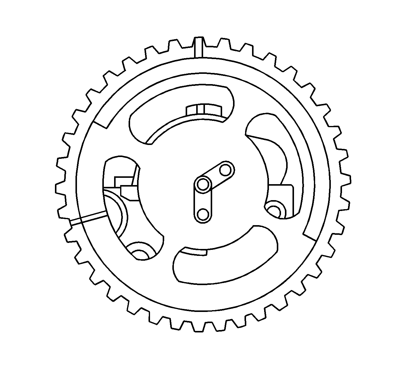
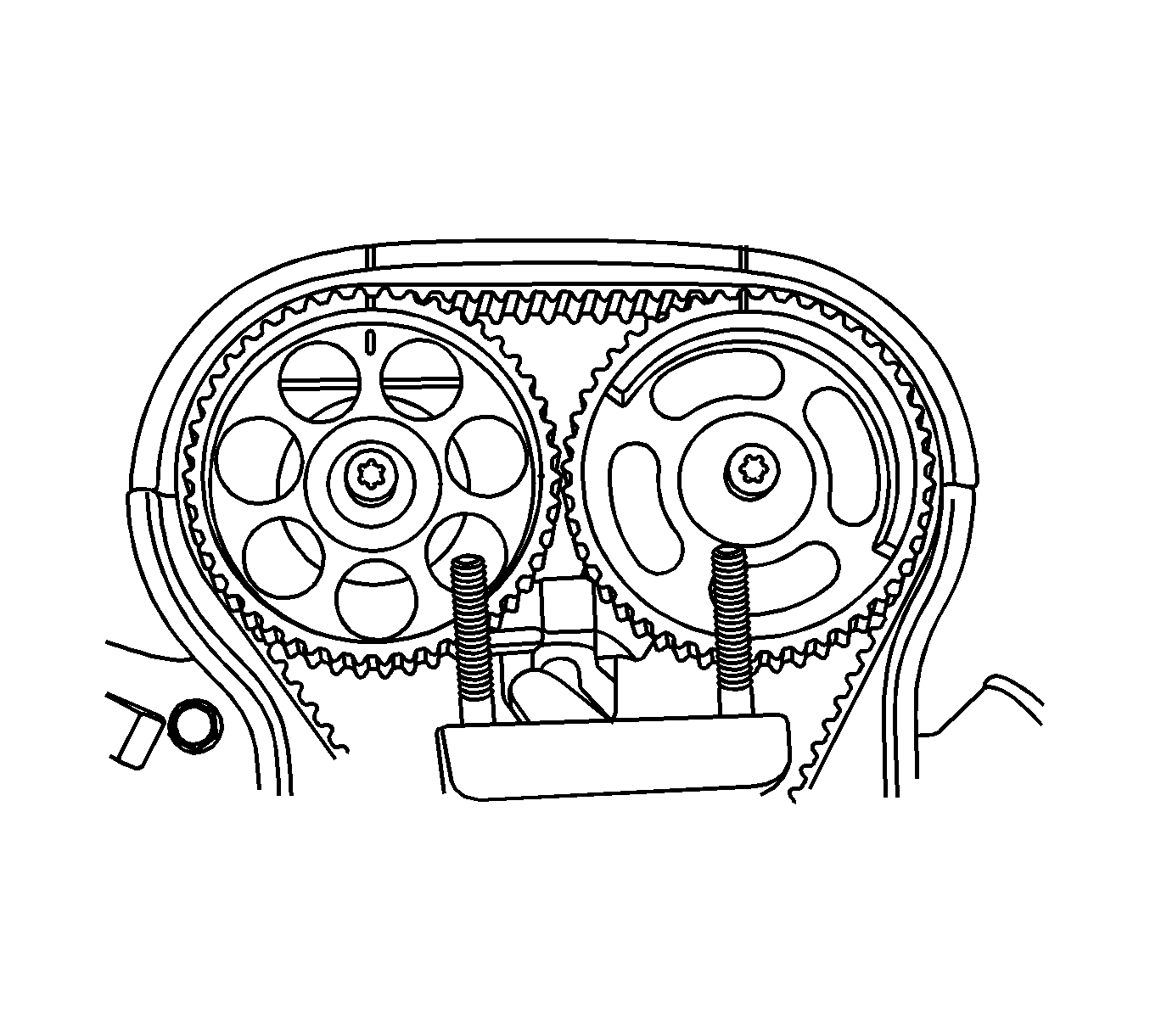
- Install the camshaft gears with the timing marks at the front.
- Insert the guide pin of the intake camshaft into the "IN" bore.
- Insert the guide pin of the exhaust camshaft into the "EX" bore.
- Install the camshaft gears by counter holding on the hex of the camshaft with an open-ended wrench.
- While holding the intake camshaft firmly in place, install a new intake camshaft gear bolt. Tighten the bolt to 50 N·m (37 lb ft) and turn the bolt another 60 degrees and 15 degrees using KM-470-B gauge .
- While holding the exhaust camshaft firmly in place, install a new exhaust camshaft gear bolt. Tighten the bolt to 50 N·m (37 lb ft) and turn the bolt another 60 degrees and 15 degrees using KM-470-B gauge .
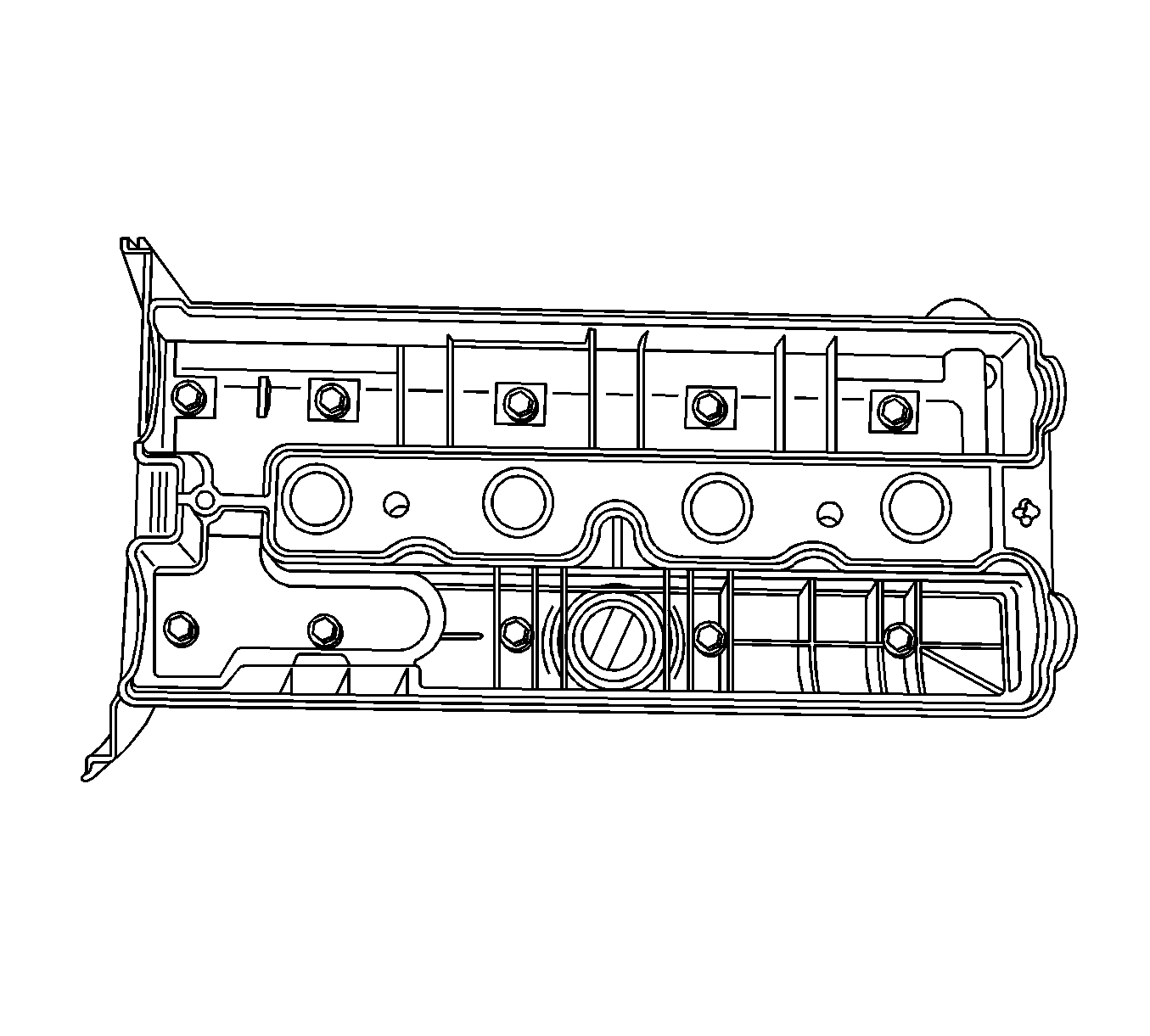
- Apply a small amount of gasket sealant to the corners of the front camshaft caps and to the top of the rear cylinder head cover-to-cylinder head seal.
- Install the cylinder head cover gasket and the cylinder head cover and tighten the bolts to 8 N·m (71 lb in). Refer to Cylinder Head Replacement.
- Connect the ignition wires to the spark plugs.
- Connect the breather hose and the PCV hose to the cylinder head cover.
- Align the timing marks on the camshaft gears to the notches on the cylinder head cover, using the intake gear mark for the intake gear and the exhaust gear mark for the exhaust gear.
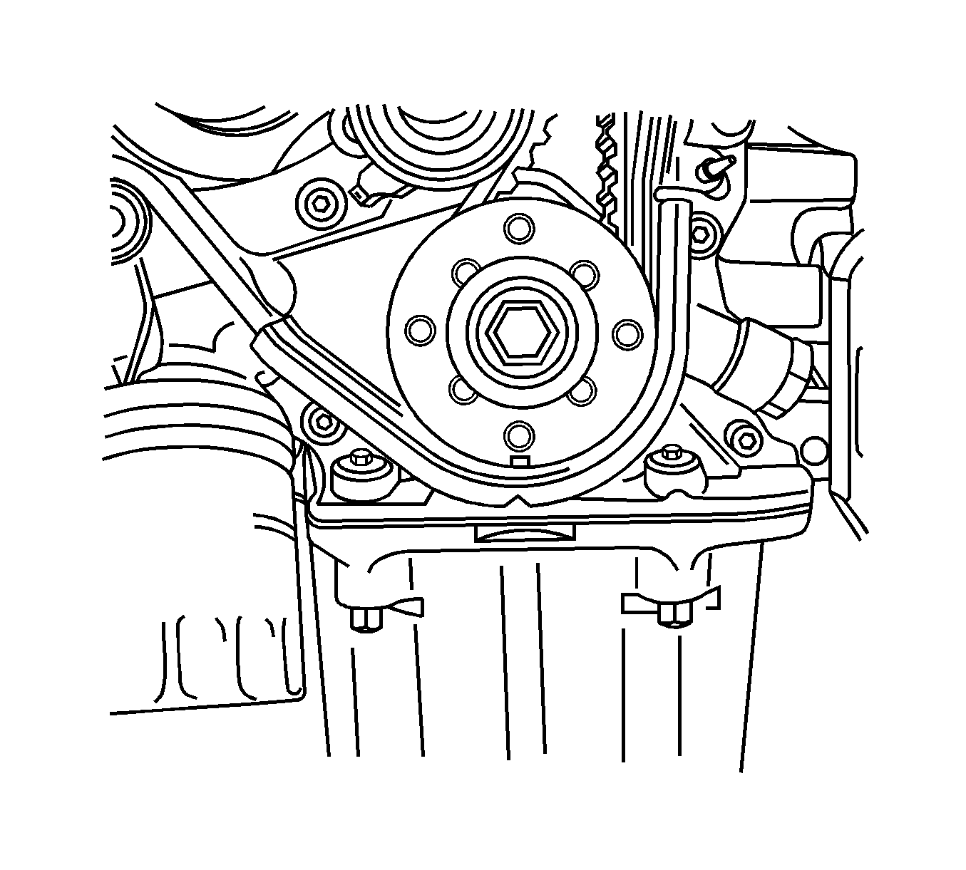
- Align the mark on the crankshaft gear with the notch at the bottom of the rear timing belt cover.
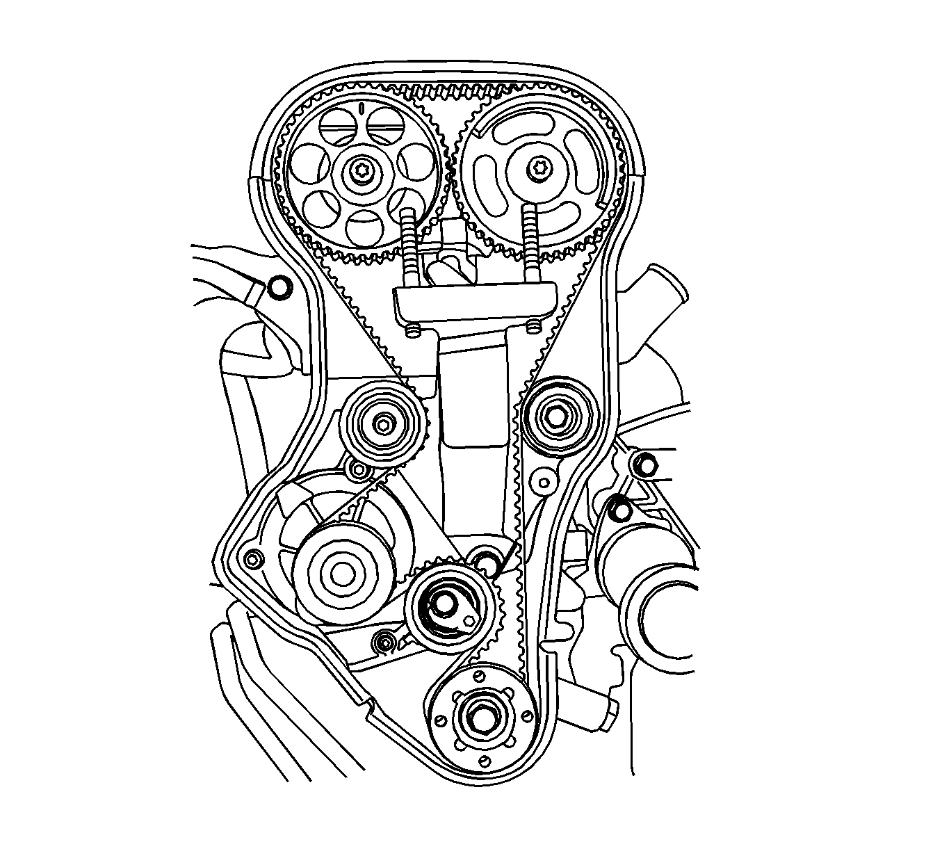
- Install the timing belt.
- Check and adjust the timing belt tension. Refer to Timing Belt Inspection and Adjustment.
- Install the front timing belt cover and tighten the bolts to 6 N·m (53 lb in).
- Install the crankshaft pulley and tighten the bolts to 23 N·m (17 lb ft).
- Install the engine mount assembly and tighten the:
- Remove the DW-110-060 fixture .
- Install the serpentine accessory drive belt. Refer to Drive Belt Replacement.
- Connect the upper radiator hose to the thermostat housing.
- Install the engine front shield at the position of right front wheel.
- Install the right front wheel. Refer to Tire and Wheel Removal and Installation.
- Install the air cleaner assembly and tighten the bolts to 10 N·m (89 lb in). Refer to Air Cleaner Assembly Replacement.
- Connect the IAT sensor connector.
- Connect the CTS sensor connector.
- Connect the ETC sensor connector.
- Connect the DIS coil connector.
- Connect the O2 sensor connector.
- Connect the EGR valve connector.
- Install the fuel pump fuse.
- Connect the negative battery cable.
- Refill the engine cooling system. Refer to Cooling System Draining and Filling.
Note: Before replacing the cylinder head, be sure to install the engine mount and then remove the DW-110-060 .
Caution: Refer to Fastener Caution in the Preface section.

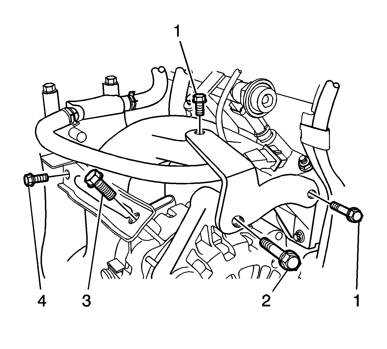
| • | retaining bolts (1) to 25 N·m (18 lb ft) |
| • | bolt (2) to 35 N·m(26 lb ft) |
| • | retaining bolt (3) to 35 N·m (26 lb ft) |
| • | bolt (4) to 25 N·m (18 lb ft) |
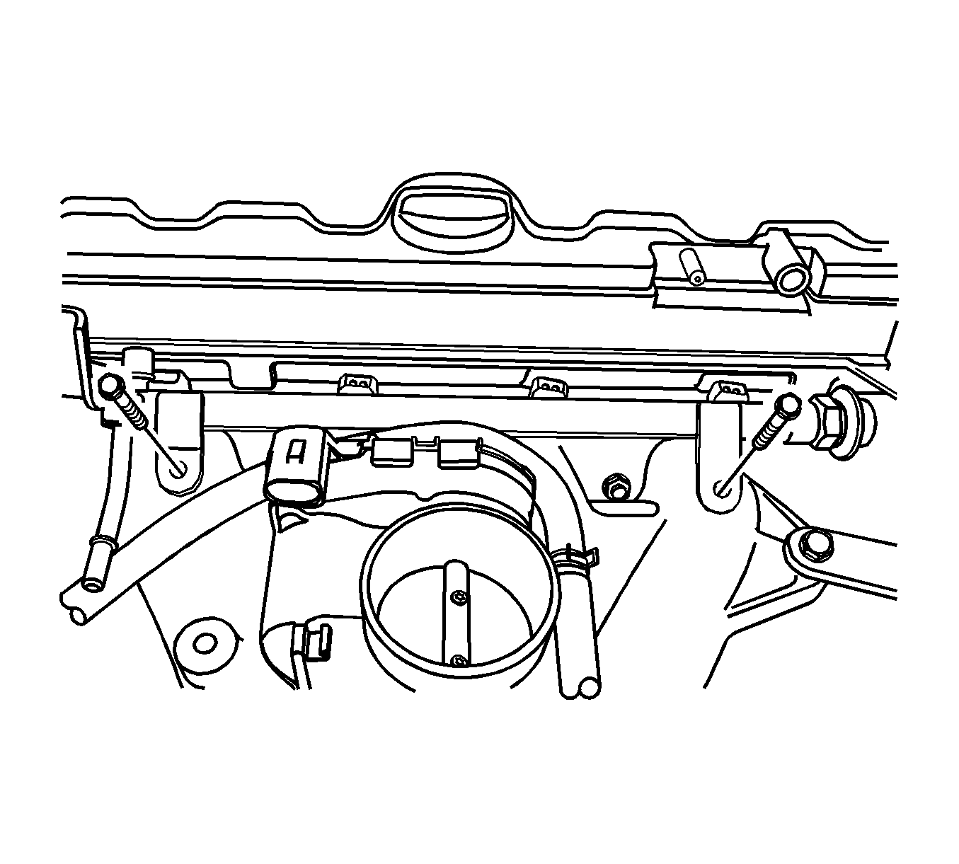


| • | pup converter-to-exhaust front pipe retaining nuts to 35 N·m (26 lb ft). |
| • | exhaust front pipe mounting bracket bolt and nut to 40 N·m (30 lb ft). |





| • | engine mount adapter bolts to 50 N·m (11 lb ft) |
| • | engine mount frame side bracket bolt to 100 N·m (74 lb ft) |
| • | nuts to 90 N·m (66 lb ft) |
| • | Refer to Engine Front Mount Replacement. |
