- Remove the transaxle from the vehicle. Refer to
Transmission Replacement.
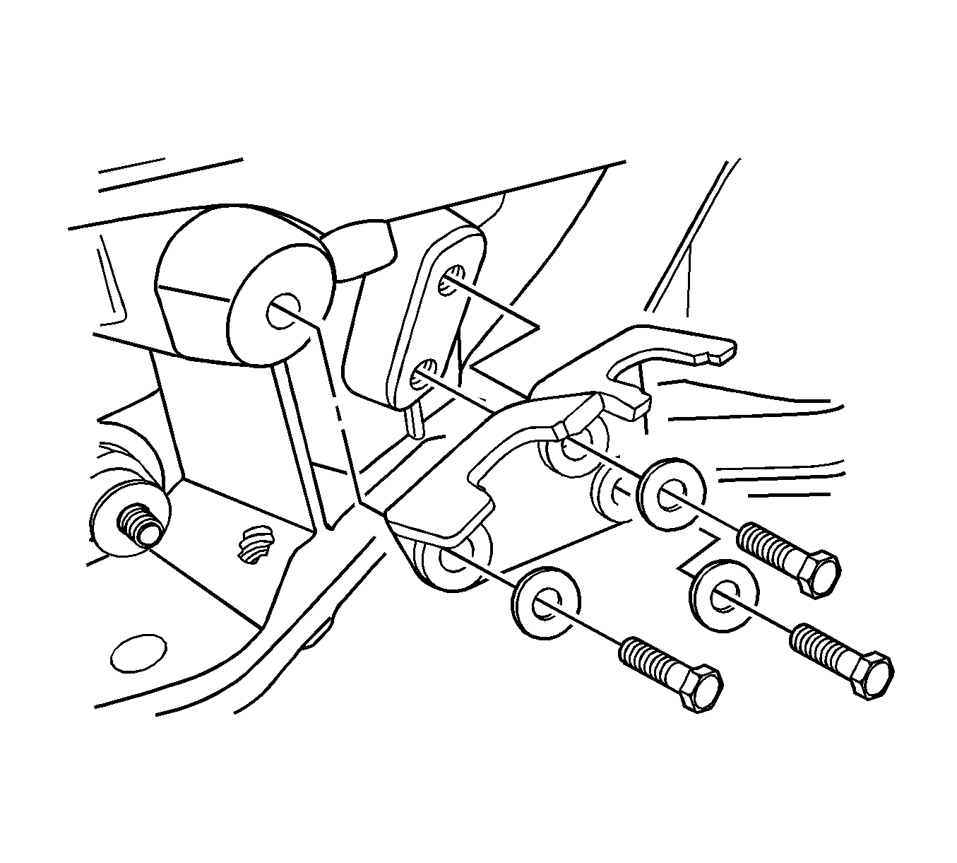
- Remove the shift control cable bracket, the washer, and the bolts.
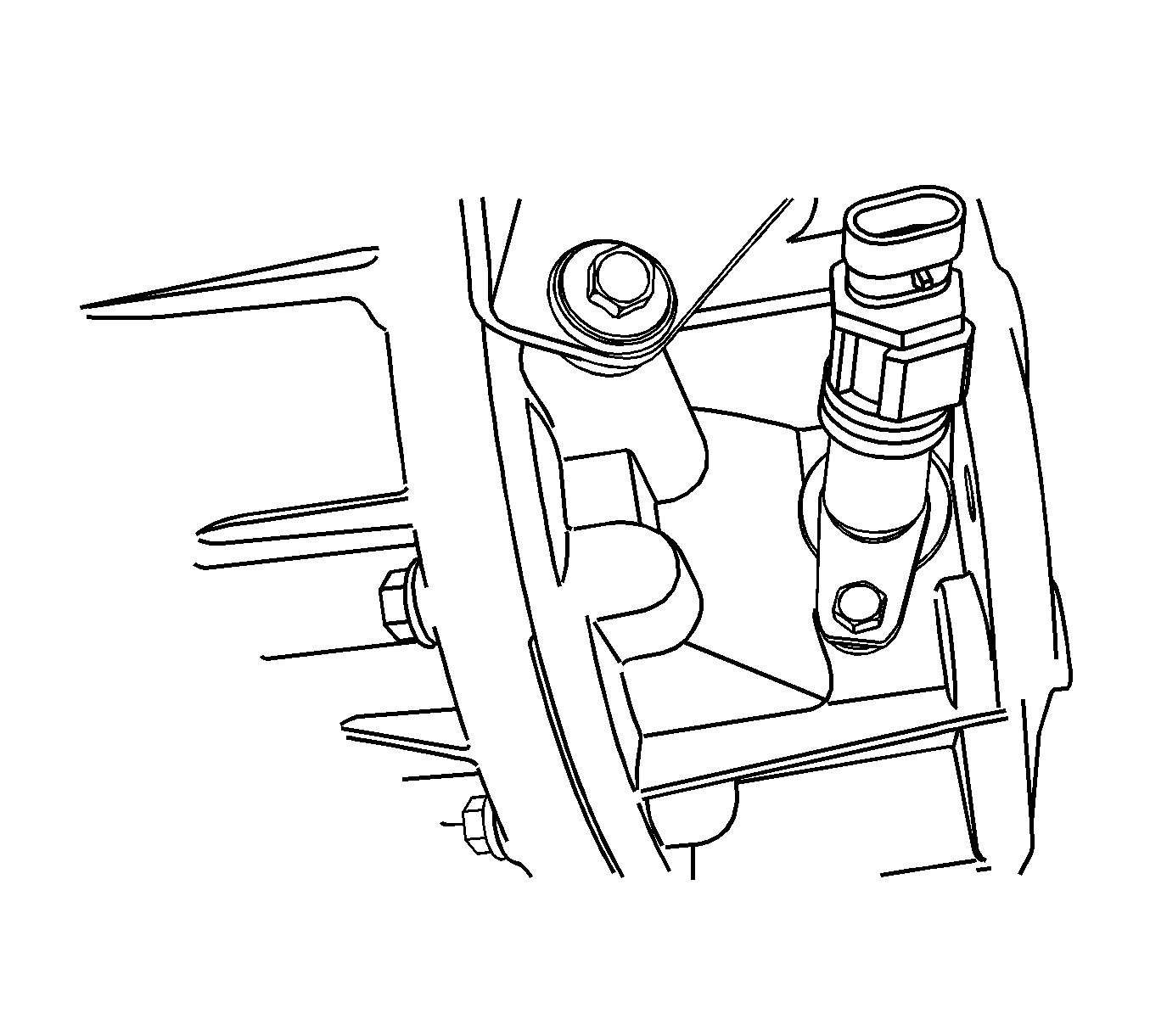
- Remove the bolt and the speedometer driven gear.
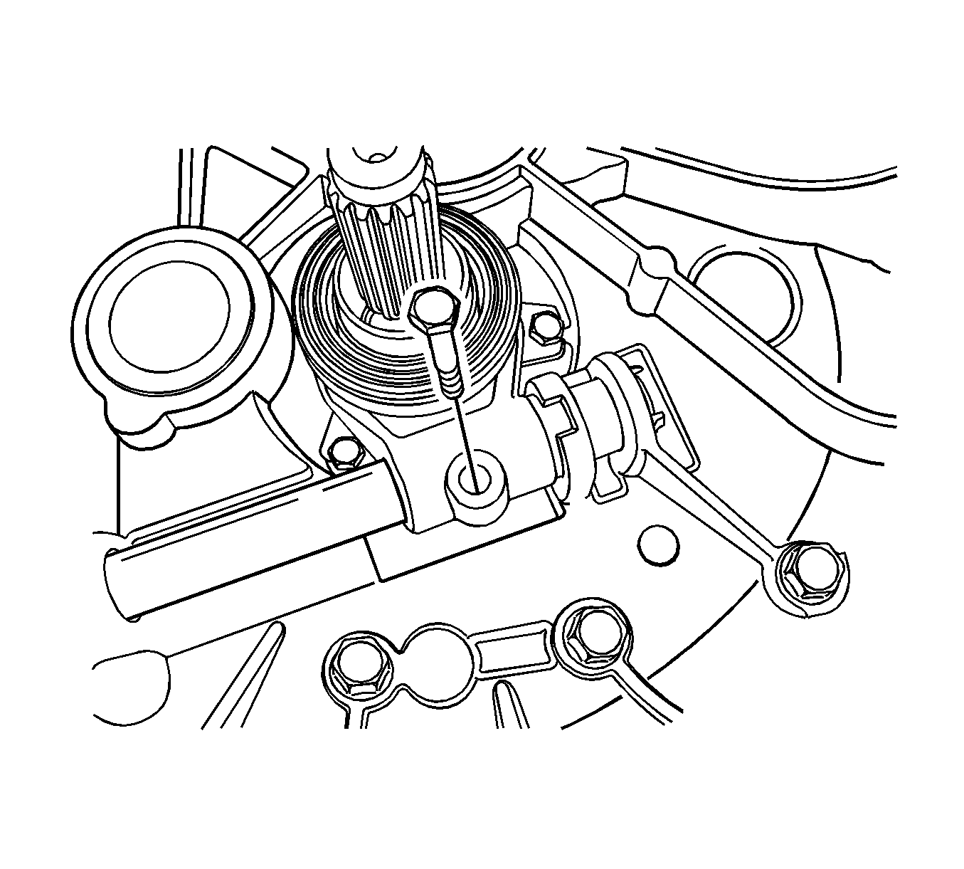
- Remove the clutch release fork bolt.
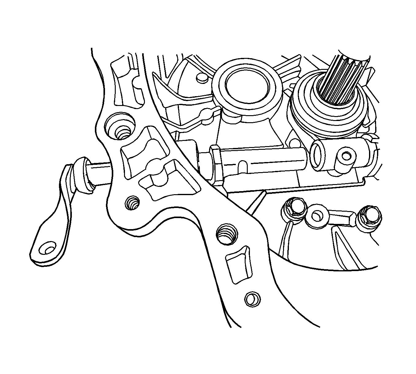
- Remove the clutch release lever.
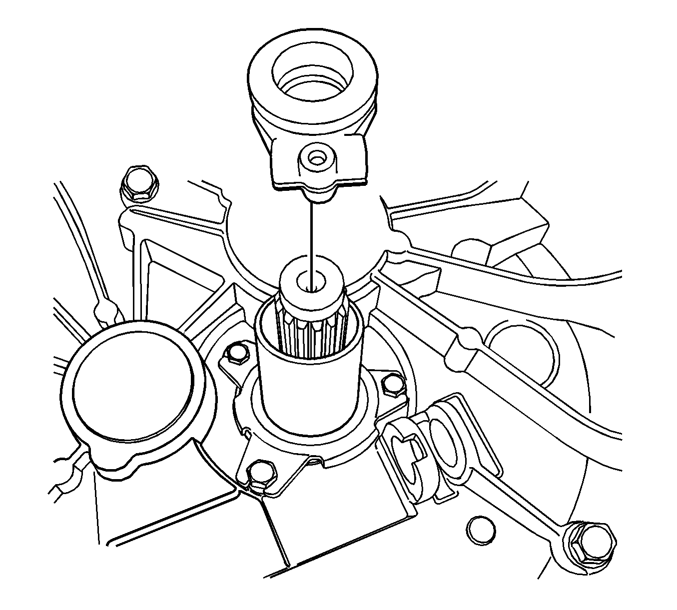
- Remove the clutch release fork and the thrust clutch bearing.
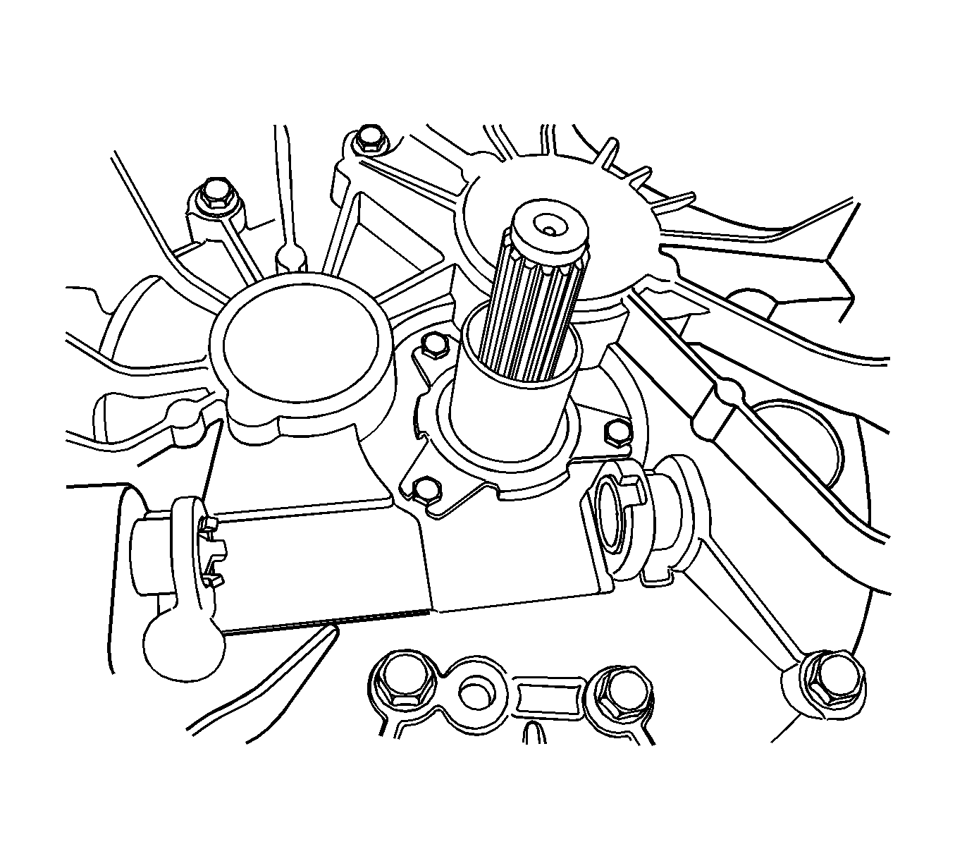
- Remove the release lever shaft bushings.
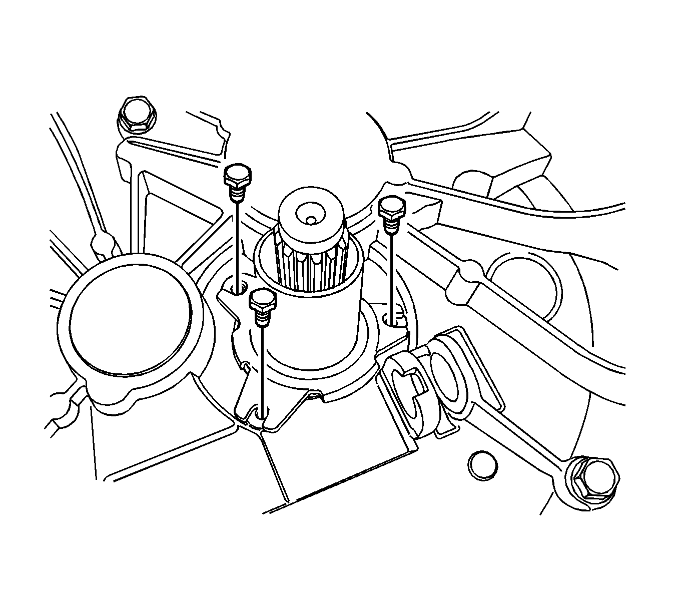
- Remove the thrust bearing guide bolts.
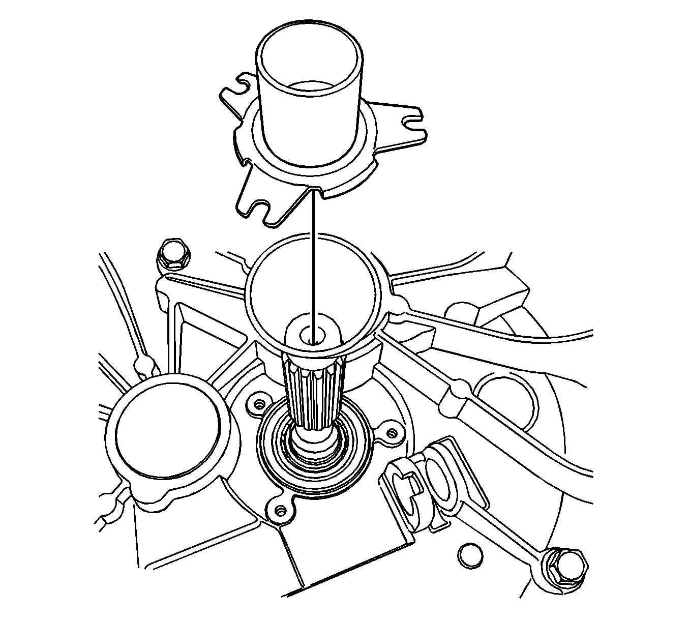
- Remove the thrust bearing guide and the O-ring.
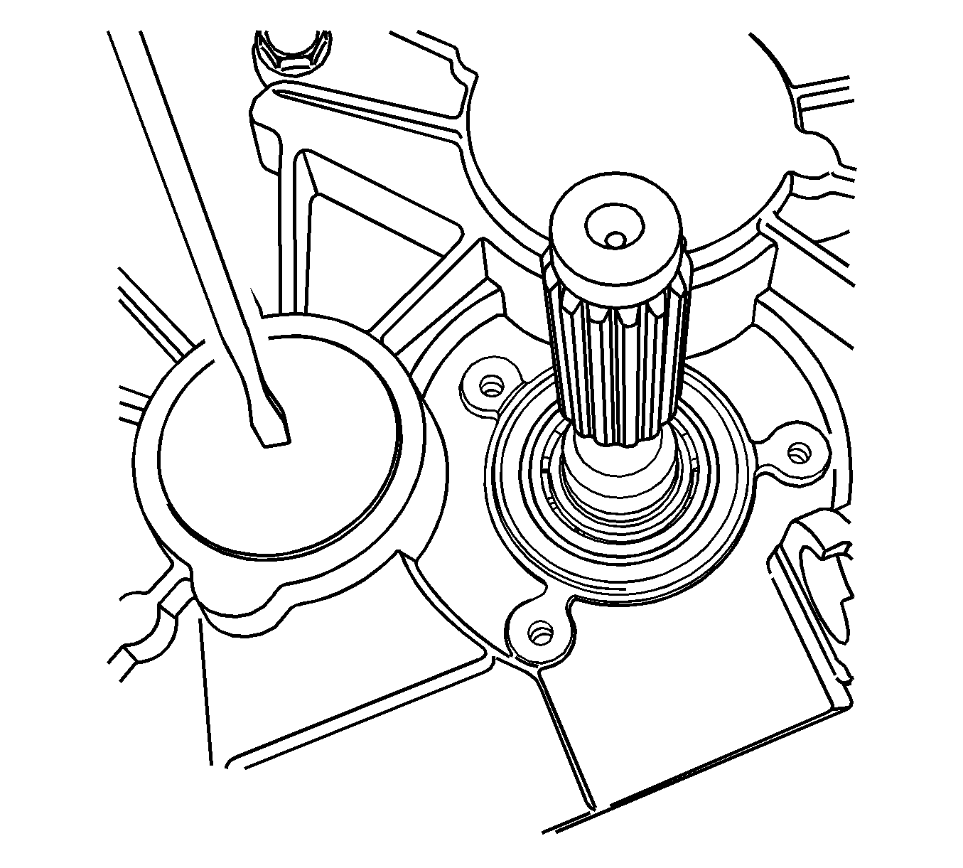
Note: Puncture the seal in the center to prevent damage to the transaxle.
- Knock a hole in the sealing plug of the interm shaft with a suitable tool.
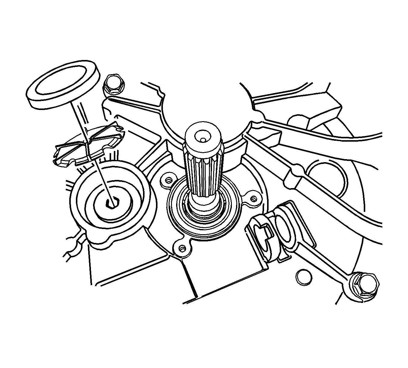
- Remove the interm shaft sealing plug and the oil pipe using a suitable tool. Discard the sealing plug and the oil pipe.
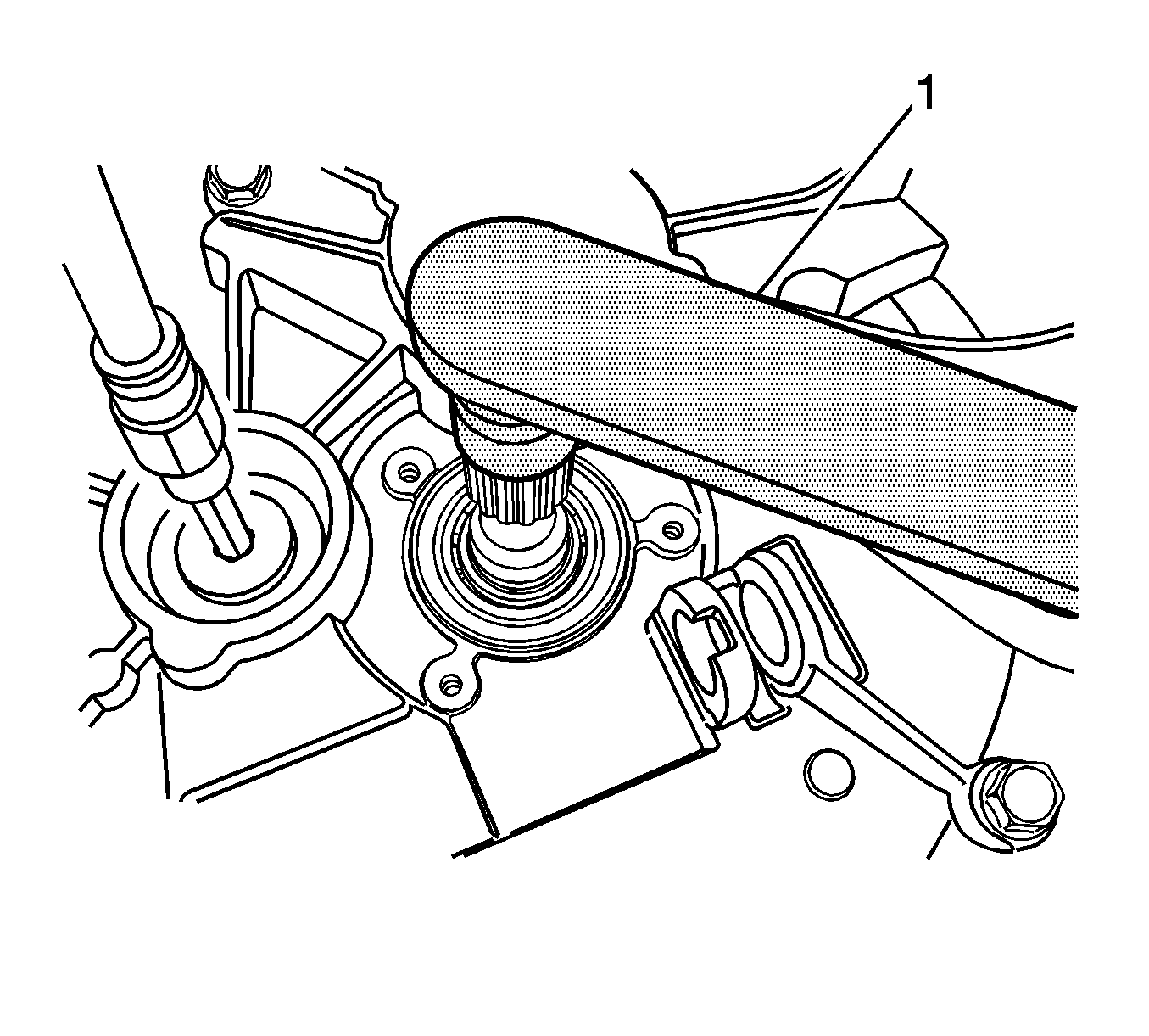
- Hold the input shaft with the
DT-48180
(1).
- Remove the retainer plug from the interm shaft. Discard the retainer plug.
Shift the transaxle into any gear.
- Remove the
DT-48180 holder
.
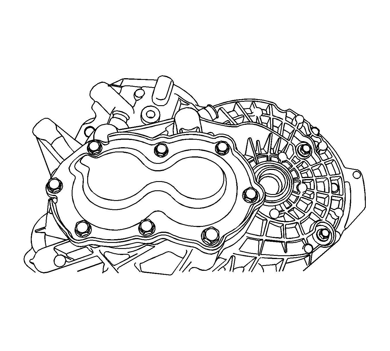
- Remove the transaxle rear cover bolts.
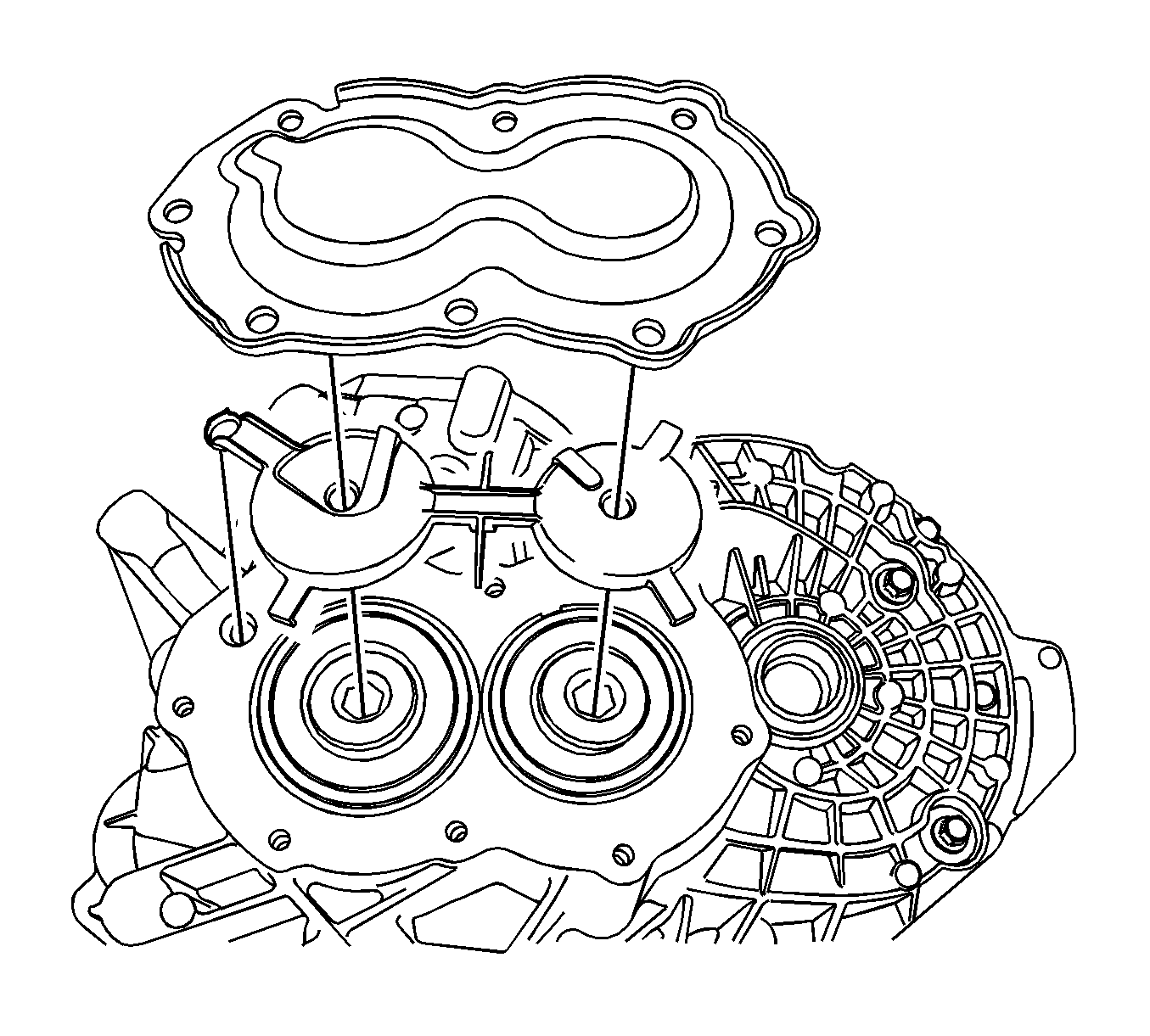
- Remove the transaxle rear cover and the oil pipe.
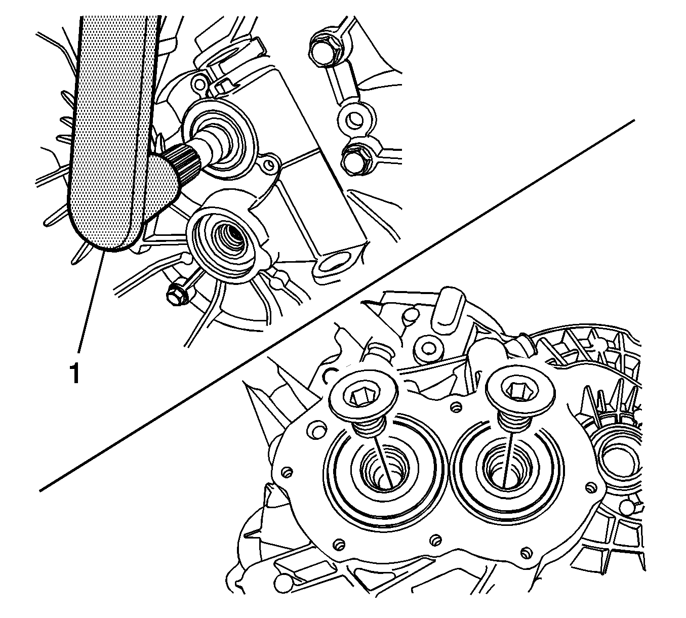
- Hold the input shaft with the
DT-48180
(1).
- Remove the input shaft retainer plug and the output shaft retainer plug. Discard the retainer plugs.
Shift the transaxle into any gear.
- Remove the
DT-48180
.
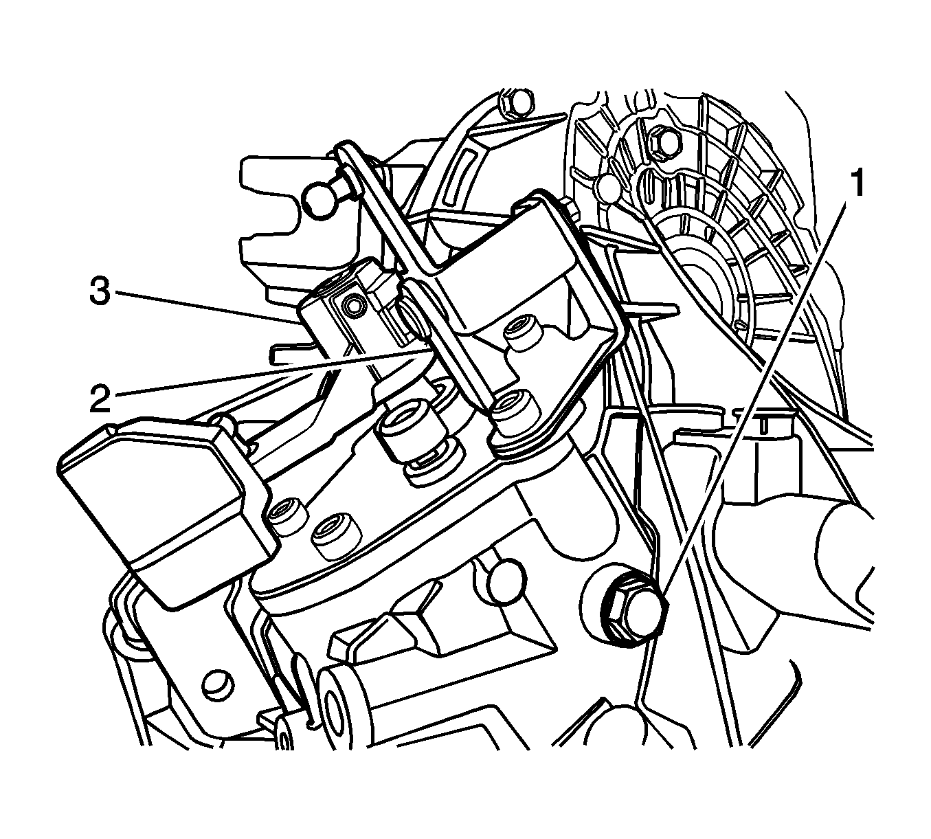
- Remove the shift shaft assembly.
| 20.1. | Position the transaxle into neutral. |
| 20.2. | Remove the shift guide bolt (1). |
| 20.3. | Remove the shift retaining bolts. |
| 20.4. | Remove the select control lever (2). |
| 20.5. | Remove the shift shaft assembly (3). |
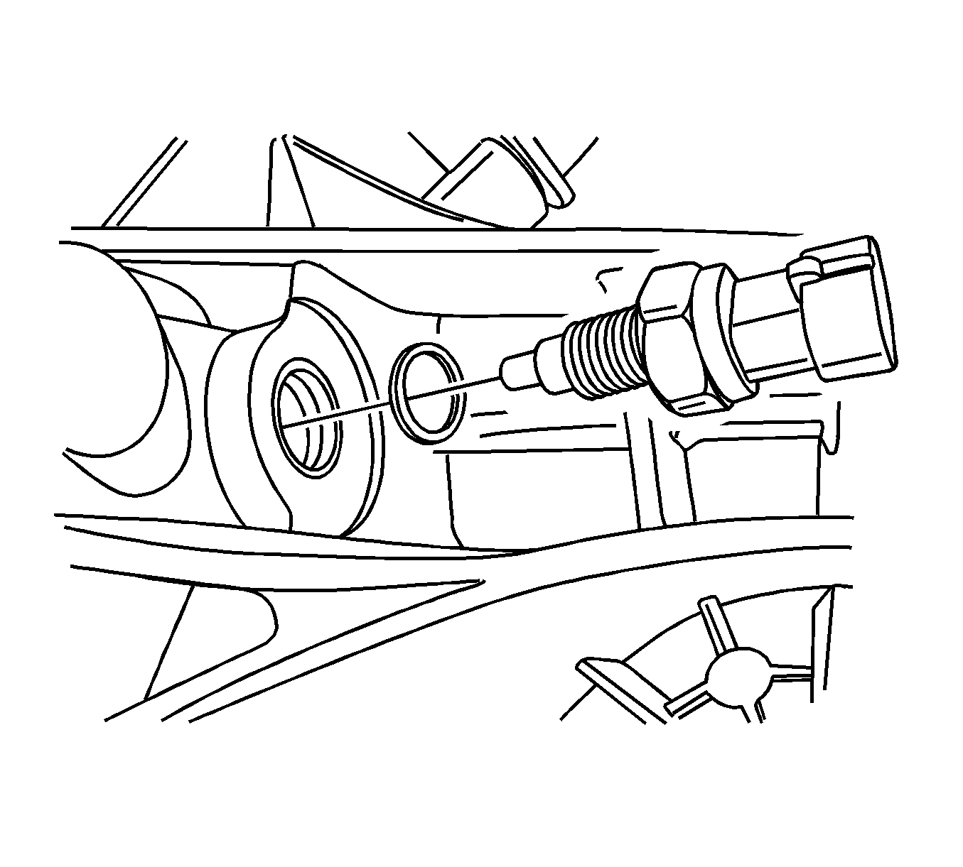
- Remove the backup lamp switch and the washer from the transaxle housing.
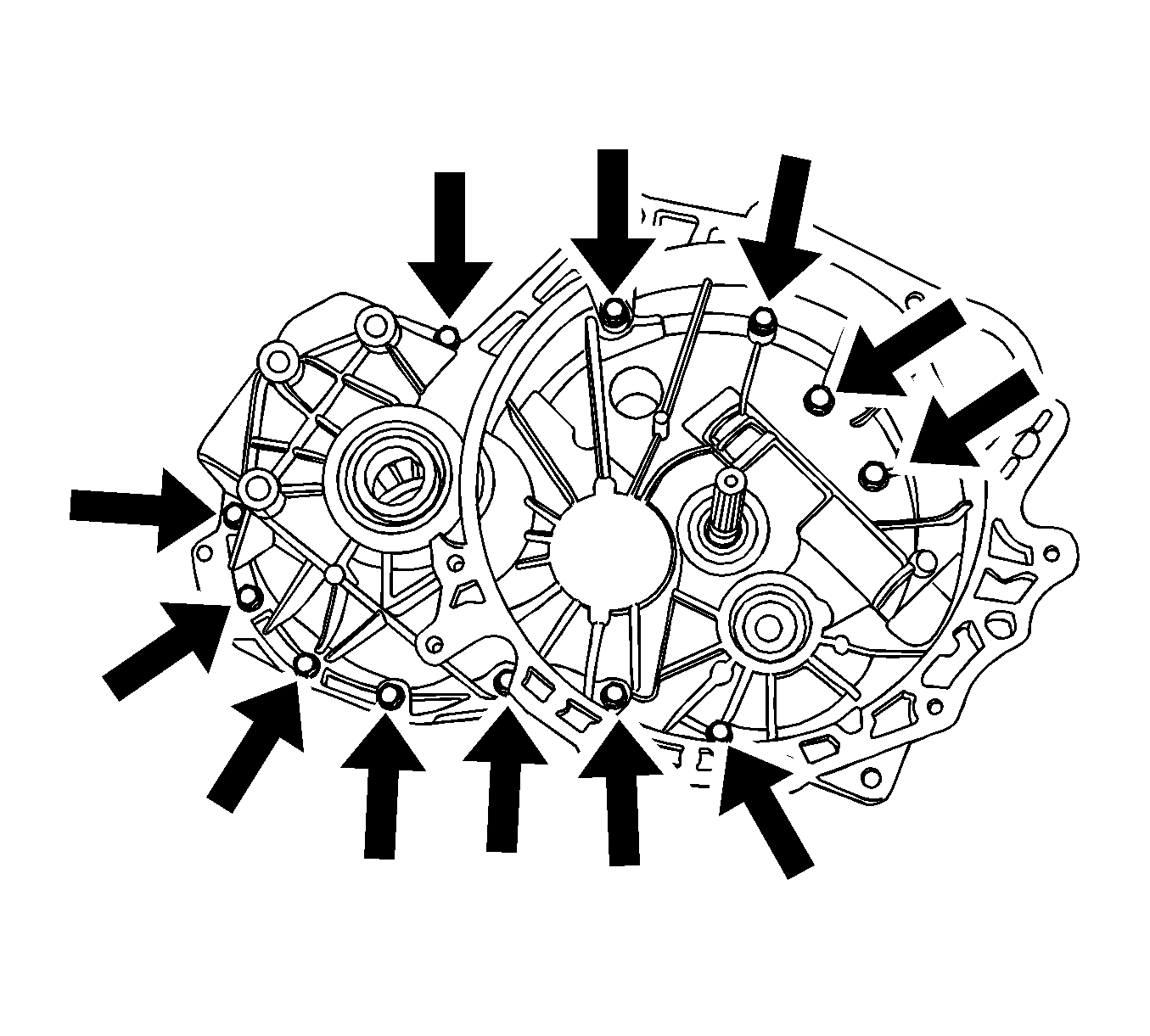
- Remove the 12 bolts from the clutch housing side.
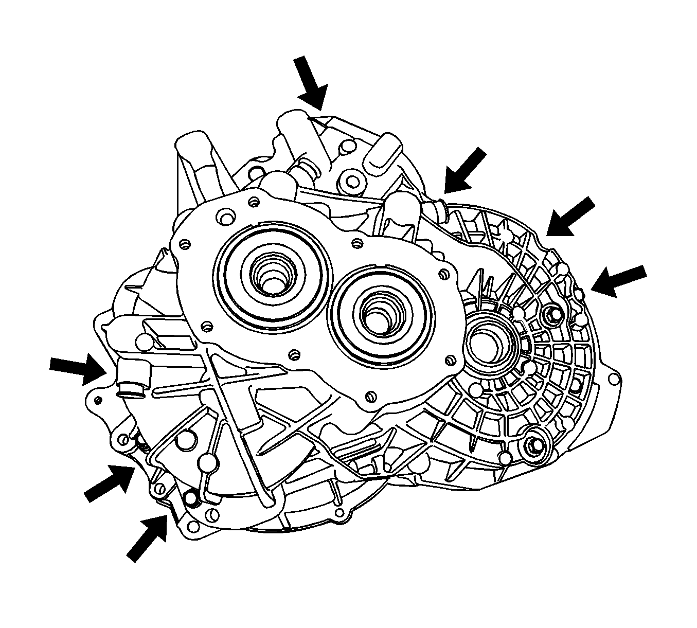
- Remove the 7 bolts from the transaxle housing side.
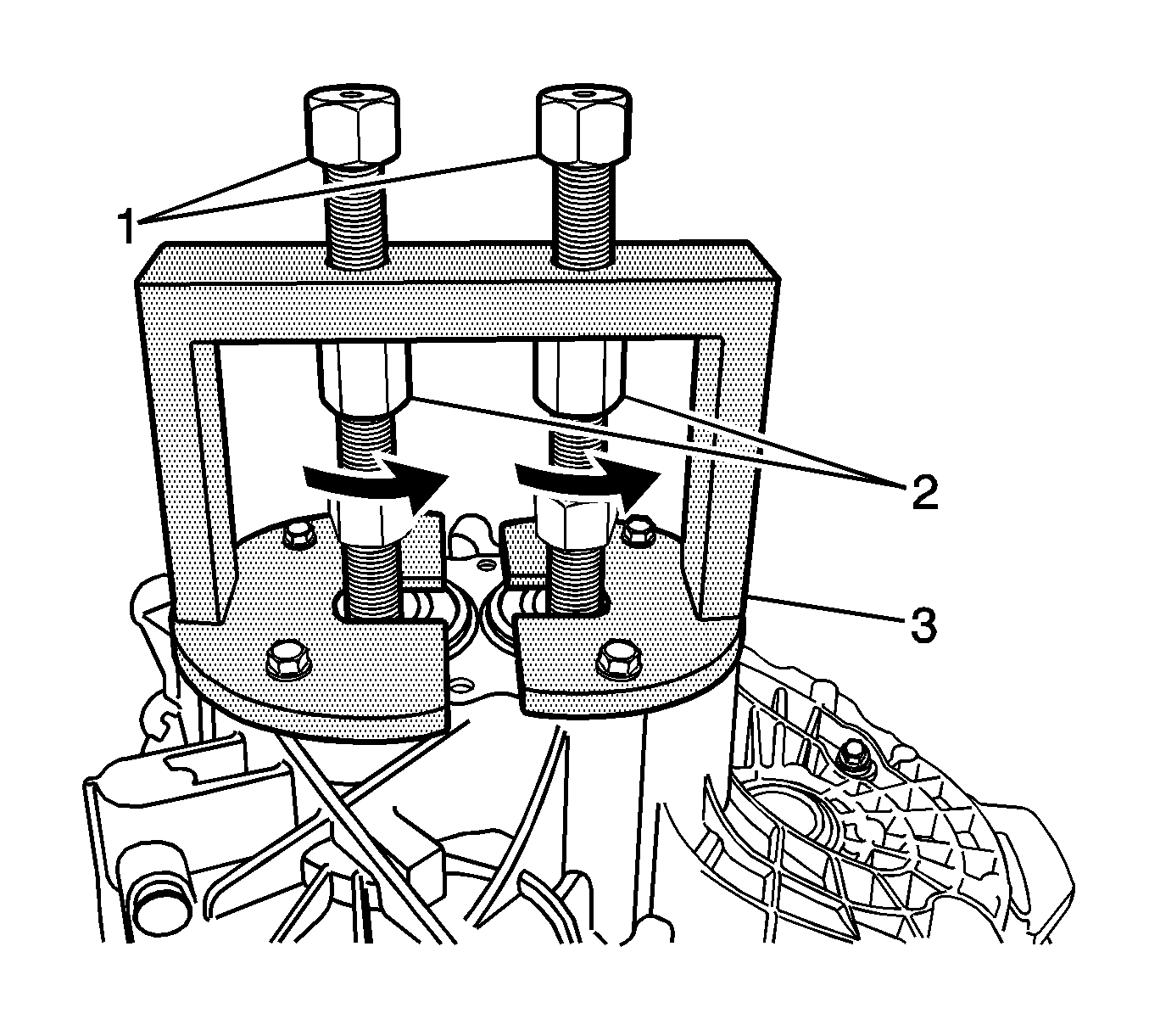
- Remove the transaxle housing from the clutch housing.
| 24.1. | Install the
DT-48188
onto the transaxle housing. |
| • | Screw the spindles into the input and output shaft. |
| 24.2. | Separate the transaxle housing from the clutch housing. |
| • | Hold the spindles (1) using a suitable tool. |
| • | Turn via nuts (2) in direction of arrow. |
| 24.3. | Remove the
DT-48188
from the transaxle housing. |
| • | Unscrew the spindles into the input and output shaft. |
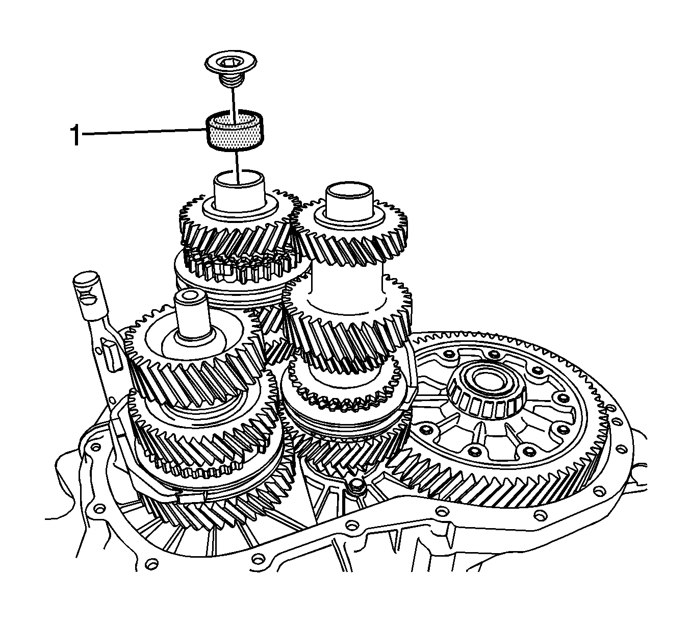
Note: This step prevents the 3rd/4th synchro body assembly falling apart.
- Install the
DT-48190
(1) and the retainer plug to the input shaft.
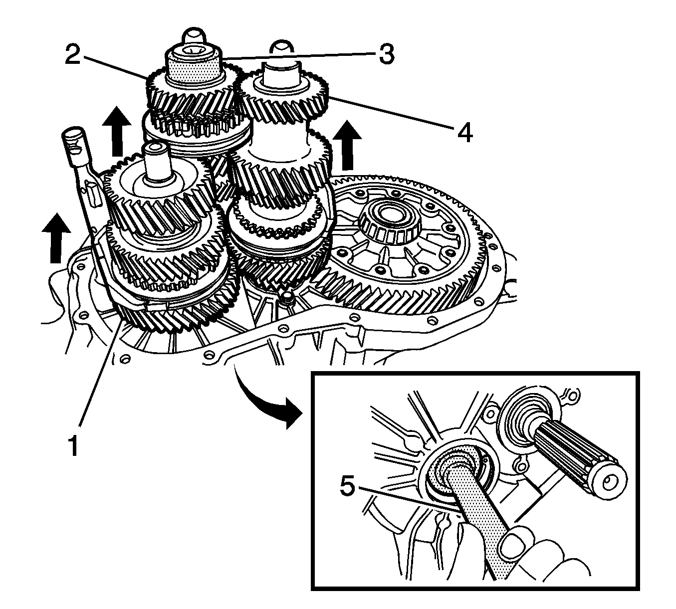
Note: Hold the input and output shaft assembly firmly.
- Remove the interm (1), input (2) and output (3) shaft assembly with the respective shift forks out of the clutch housing.
| 26.1. | Knock interm shaft out of interm shaft groove ball bearing using the
DT-48186
. |
| 26.2. | Remove the output shaft assembly and the shift fork. |
| 26.3. | Remove the interm and input shaft assembly with the respective shift forks. |
- Remove the
DT-48190
and the retainer plug from the input shaft.
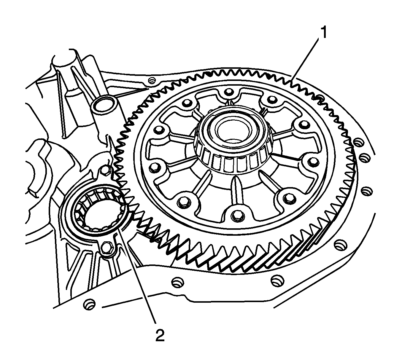
- Remove the differential (1) and the output shaft roller bearing (2) from the clutch housing.
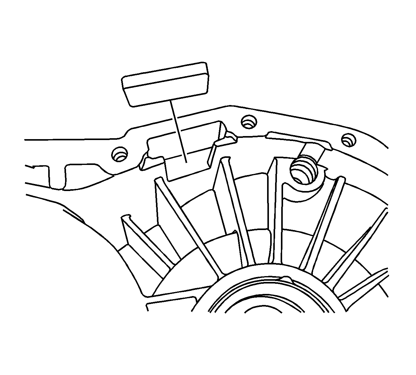
- Remove the magnet from the transaxle housing.
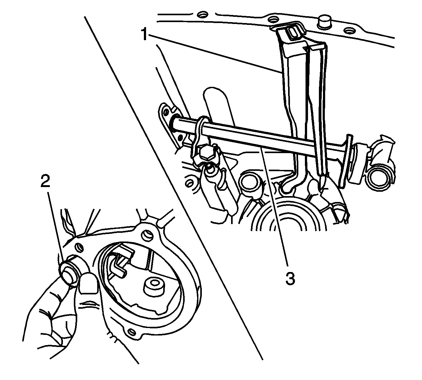
- Remove the drain channel (1) from the transaxle housing.
- Remove the idle shift rail bushing (2) from the transaxle housing.
- Remove the idle shift rail (3) from the transaxle housing.
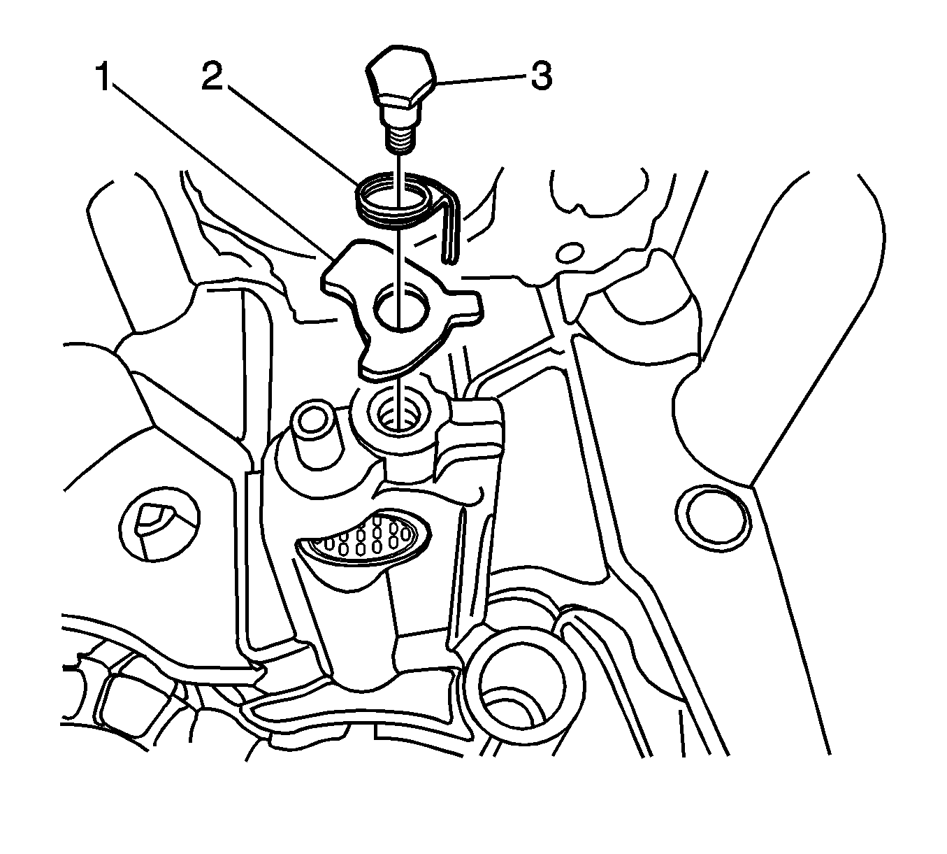
- Remove the thread pin (3), the torsion spring (2), and the reverse shifting blocker (1) from the transaxle housing. Discard the thread
pin.
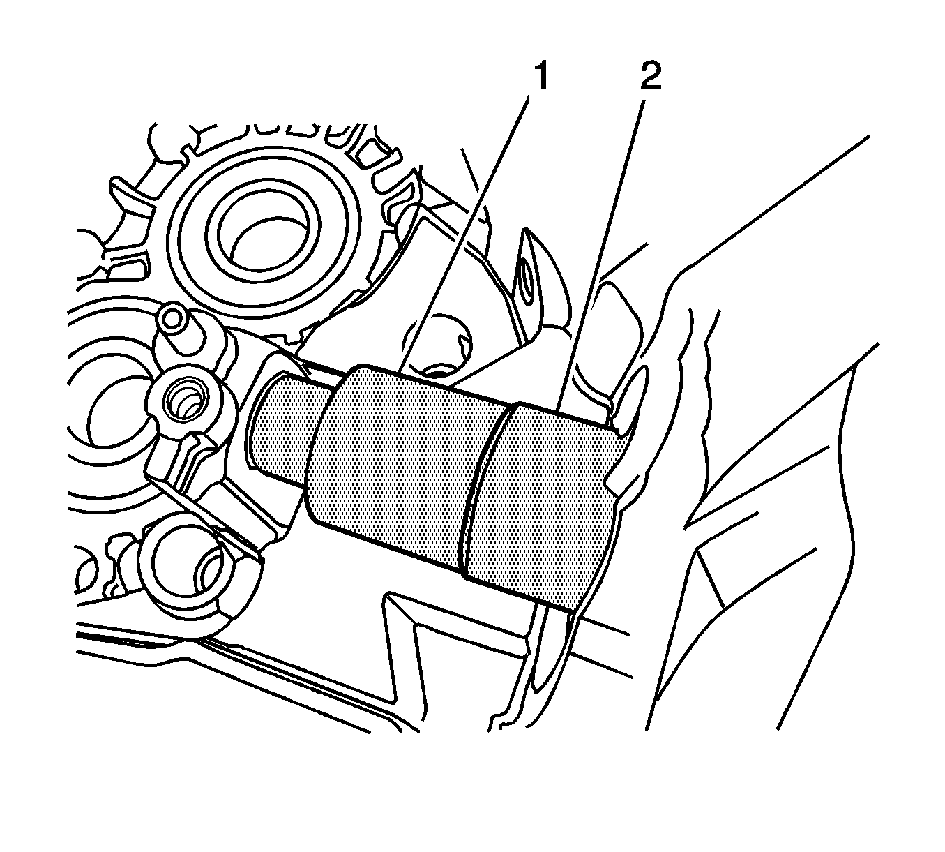
- Remove the needle sleeve from the transaxle housing using the
DT-48179
(2) and the
DT-48182
(1).
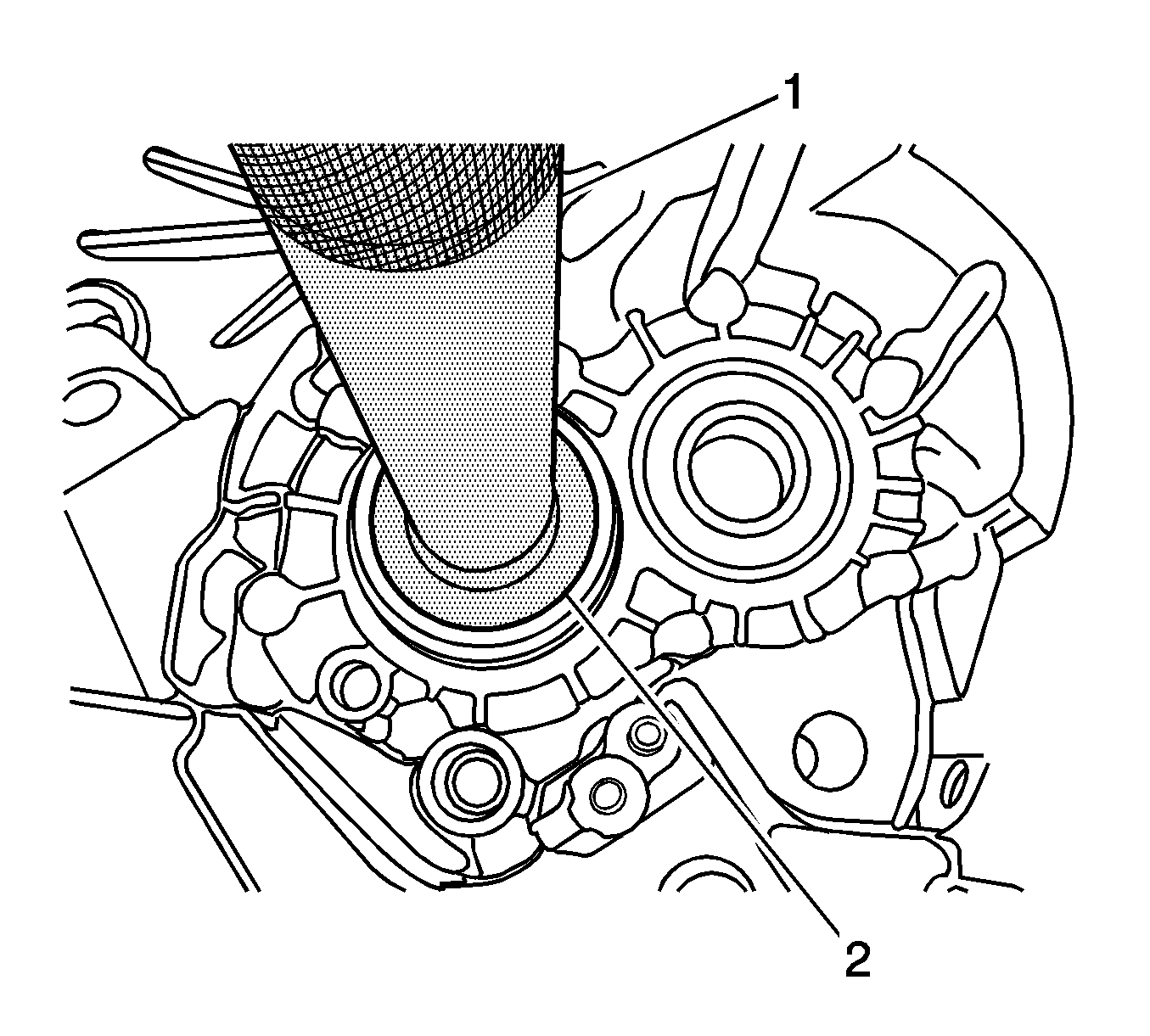
- Remove the input shaft and output shaft groove ball bearings from the transaxle housing using the
DT-48179
(1) and the
DT-48181
(2).
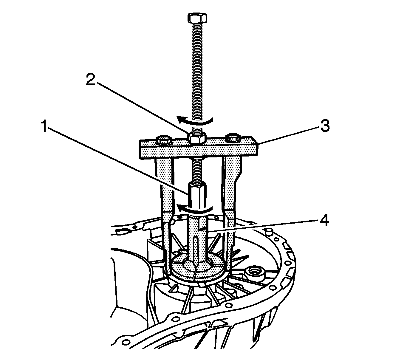
- Remove the differential bearing race from the transaxle housing.
| 36.2. | Turn the nut (1) in the direction of the arrow. |
| 36.4. | Hold the spindle using a suitable tool. |
| 36.5. | Turn the nut (2) in the direction of the arrow. |
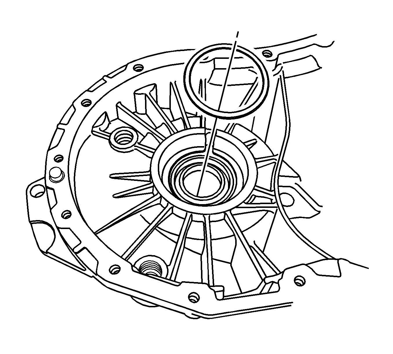
- Remove the shim from the transaxle housing.
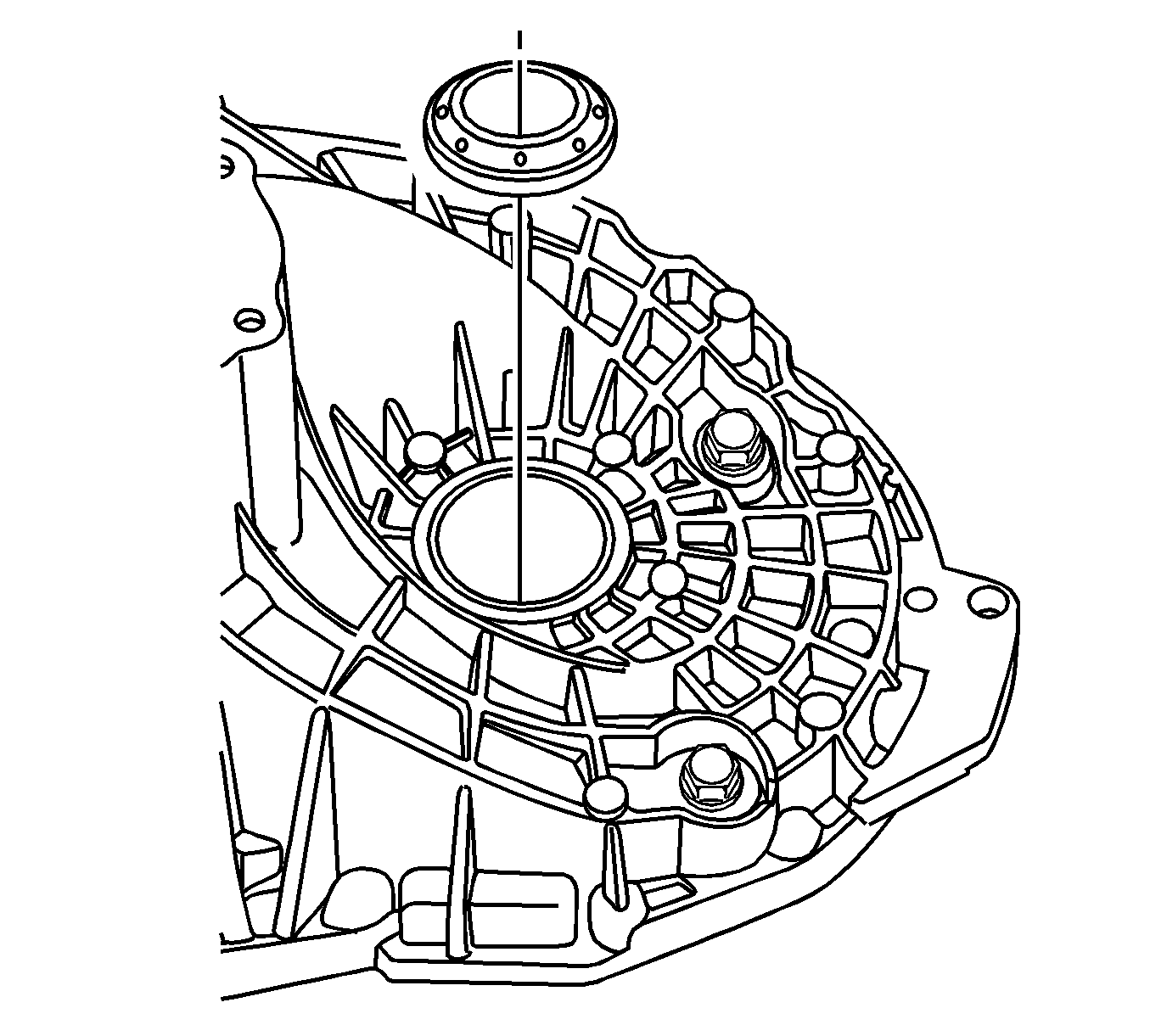
- Remove the shaft seal ring from the transaxle housing. Discard the shaft seal ring.
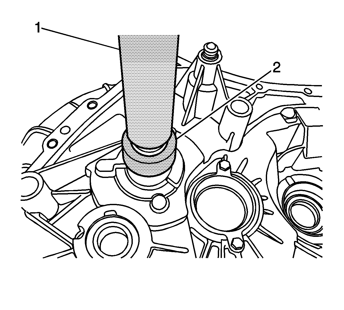
- Remove the input shaft roller bearing from the clutch housing using the
DT-48179
(1)
and the
DT-48184
(2).
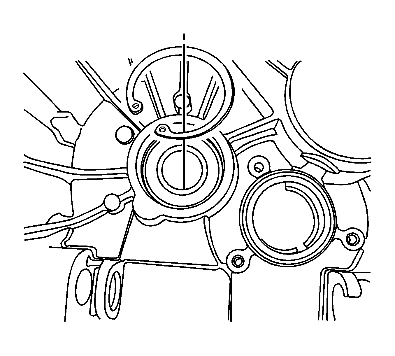
- Remove the snap ring from the interm shaft groove ball bearing.
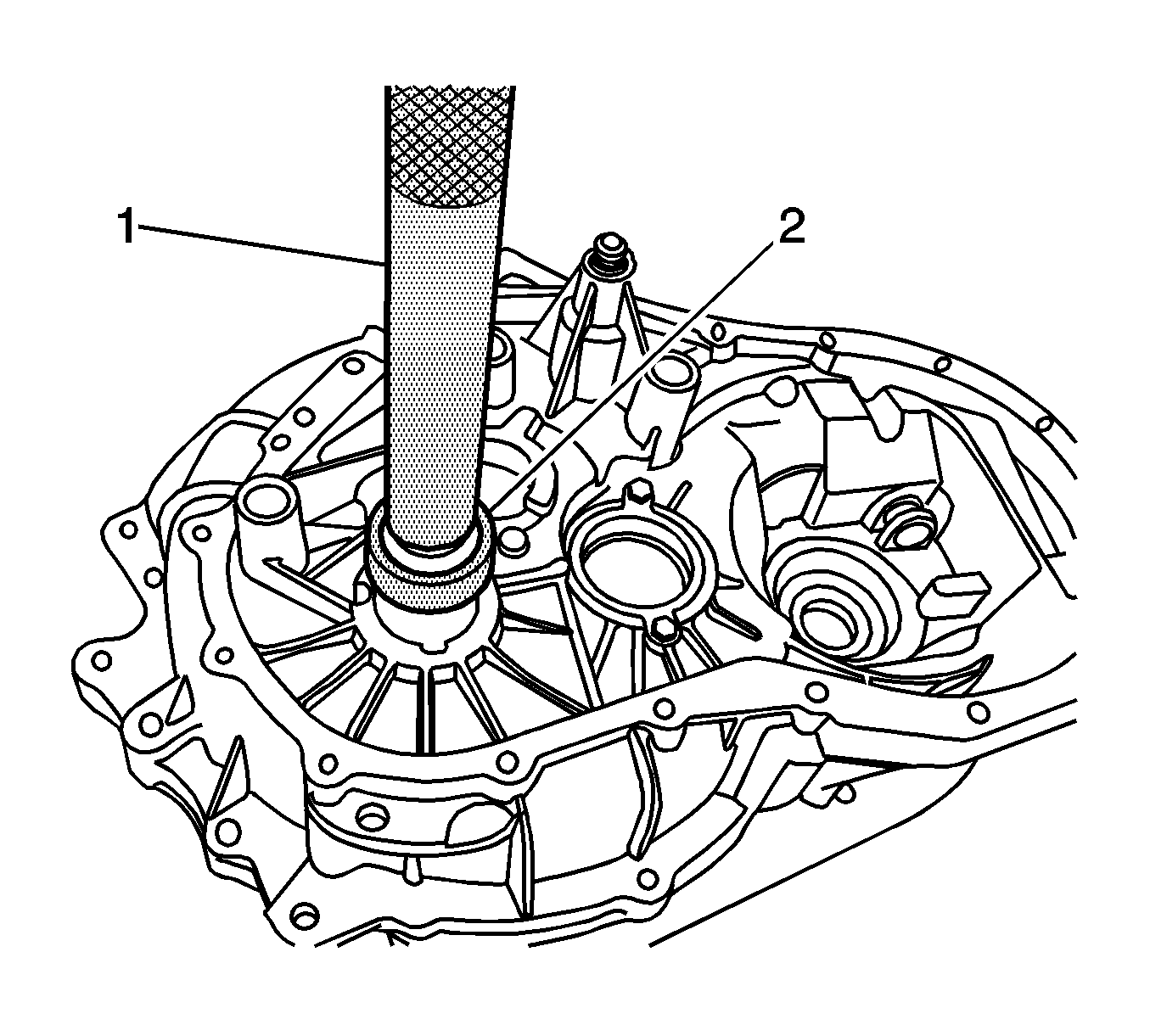
- Remove the interm shaft groove ball bearing from the clutch housing using the
DT-48179
(1) and the
DT-48184
(2).
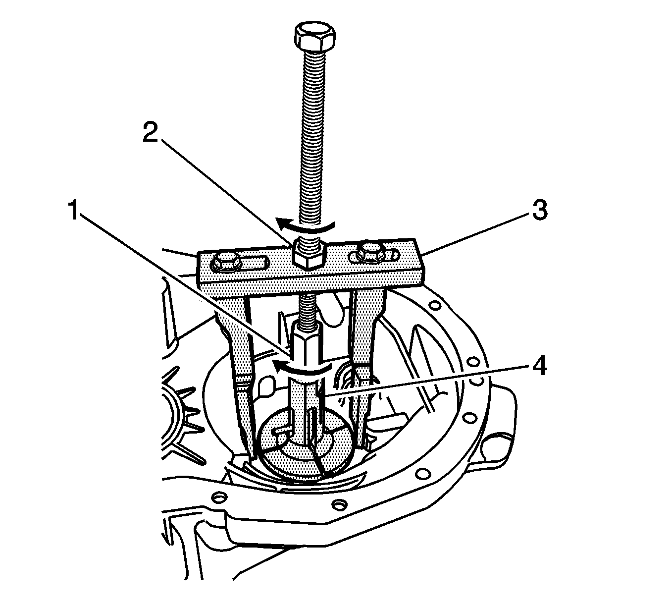
- Remove the differential bearing race from the clutch housing.
| • | Turn the nut (1) in the direction of the arrow. |
| • | Hold the spindle using a suitable tool. |
| • | Turn the nut (2) in the direction of the arrow. |
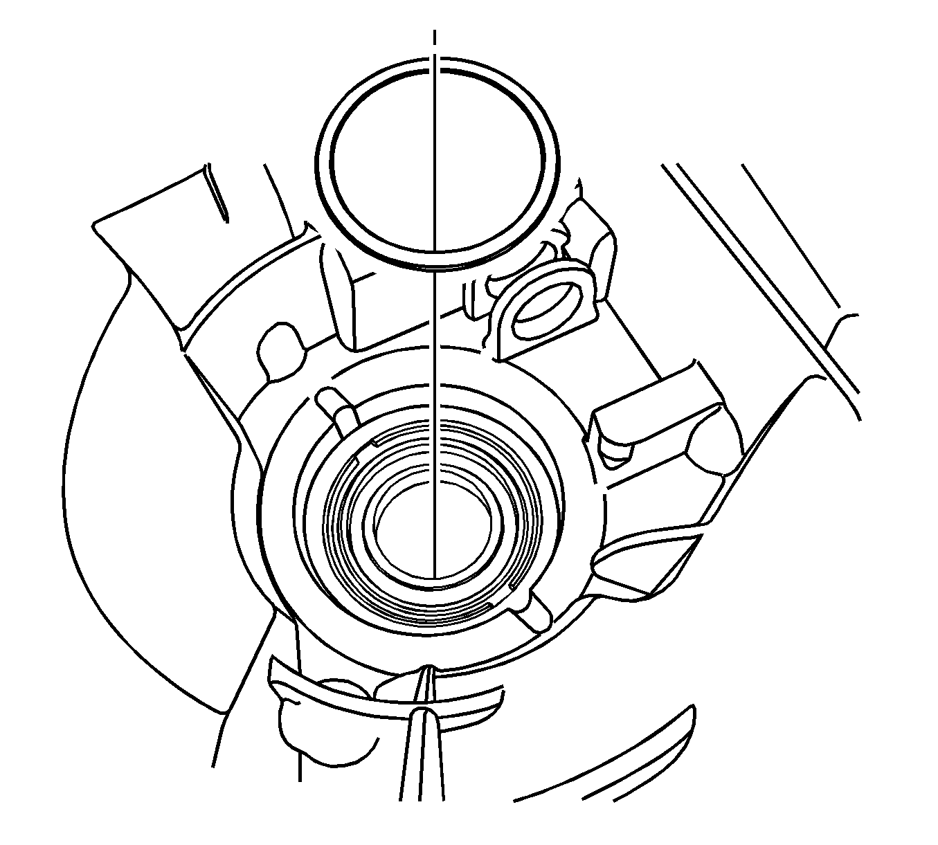
- Remove the shim from the clutch housing.
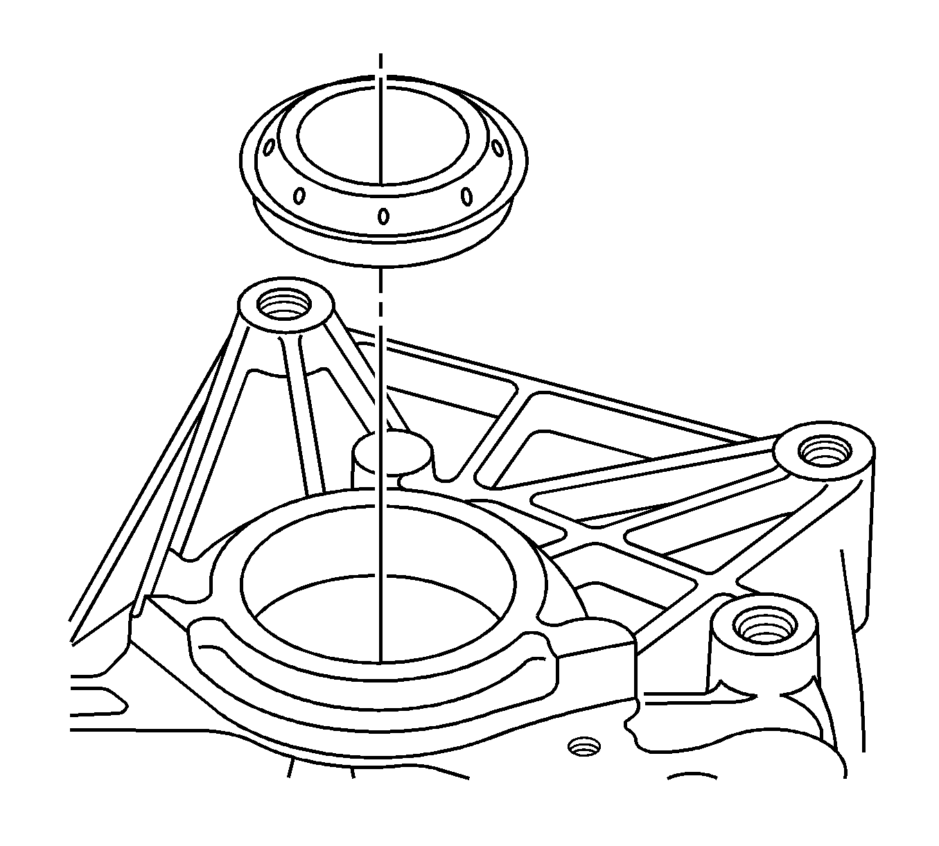
- Remove the shaft seal ring from the clutch housing. Discard the shaft seal ring.
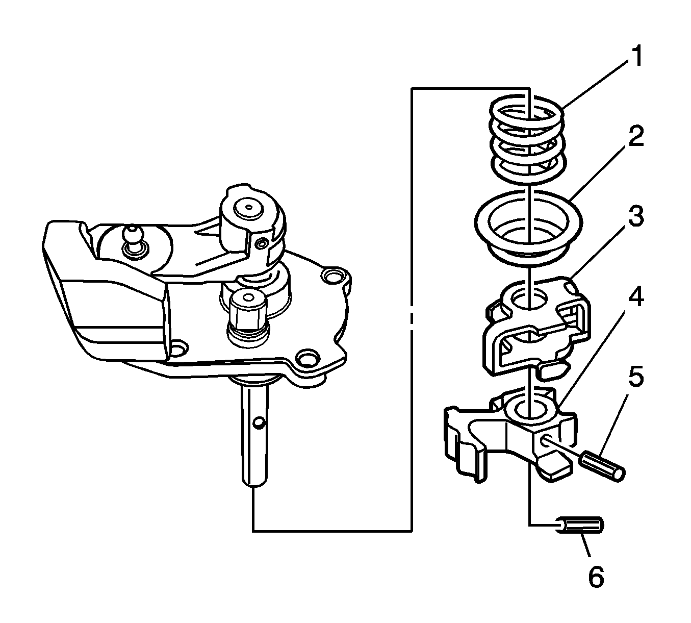
Note: Observe the orientation of the coiled pin before removal.
- Remove the coiled pin (6). Discard the coiled pin.
- Remove the coiled pin (5). Discard the coiled pin.
- Remove the shift interlock (3).
- Remove the shift finger (4).
- Remove the outer spring seat (2).
- Remove the 5th/reverse pressure spring (1).
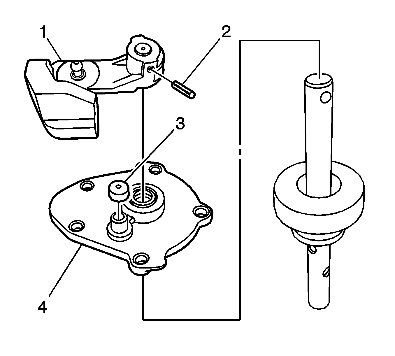
- Remove the coiled pin (2). Discard the coiled pin.
- Remove the shift lever (1).
- Remove the vent cap (3).
- Remove the shift cover (4).
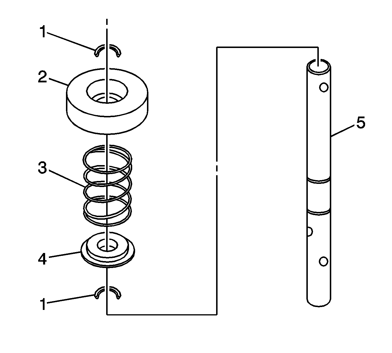
- Remove the snap rings (1). Discard the snap rings.
- Remove the inner spring seat (2).
- Remove the 1st/2nd pressure spring (3).
- Remove the angle disc (4) from the shift rod (5).
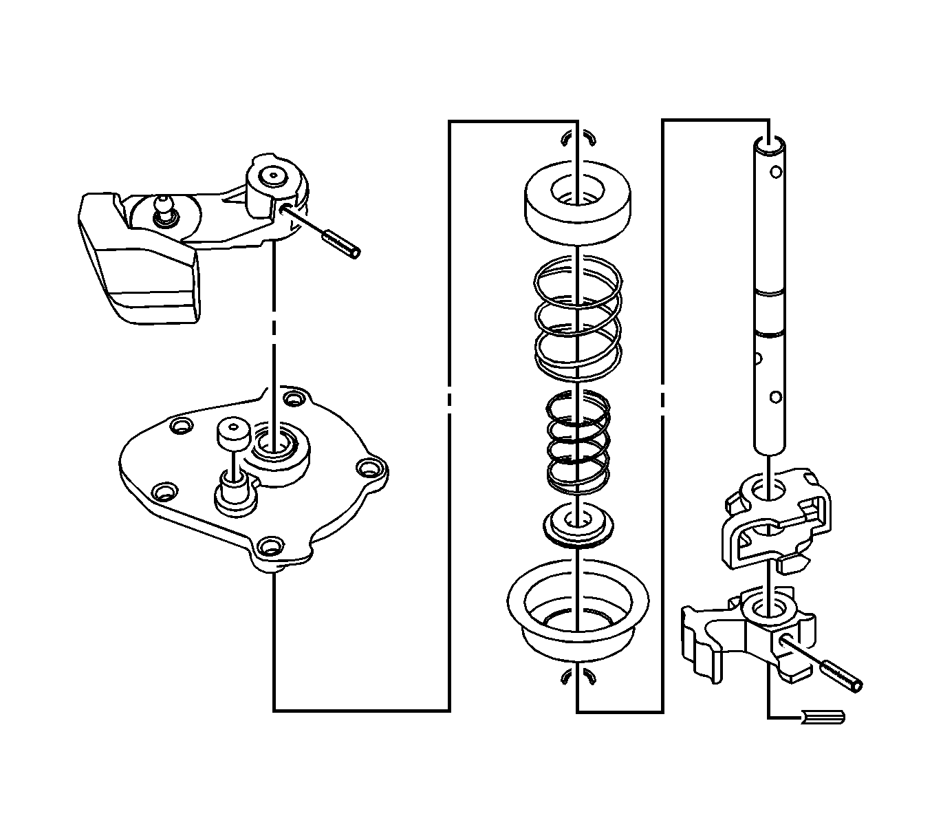
- Clean all components in a suitable solution.
- Inspect all components for wear or damage.
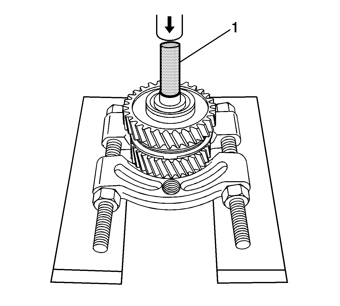
- Press off the 1st gear assembly and the 2nd gear assembly as a unit, from the interm shaft using the gear and bearing separator plate, the
DT-48191
(1) , and a hydraulic press.
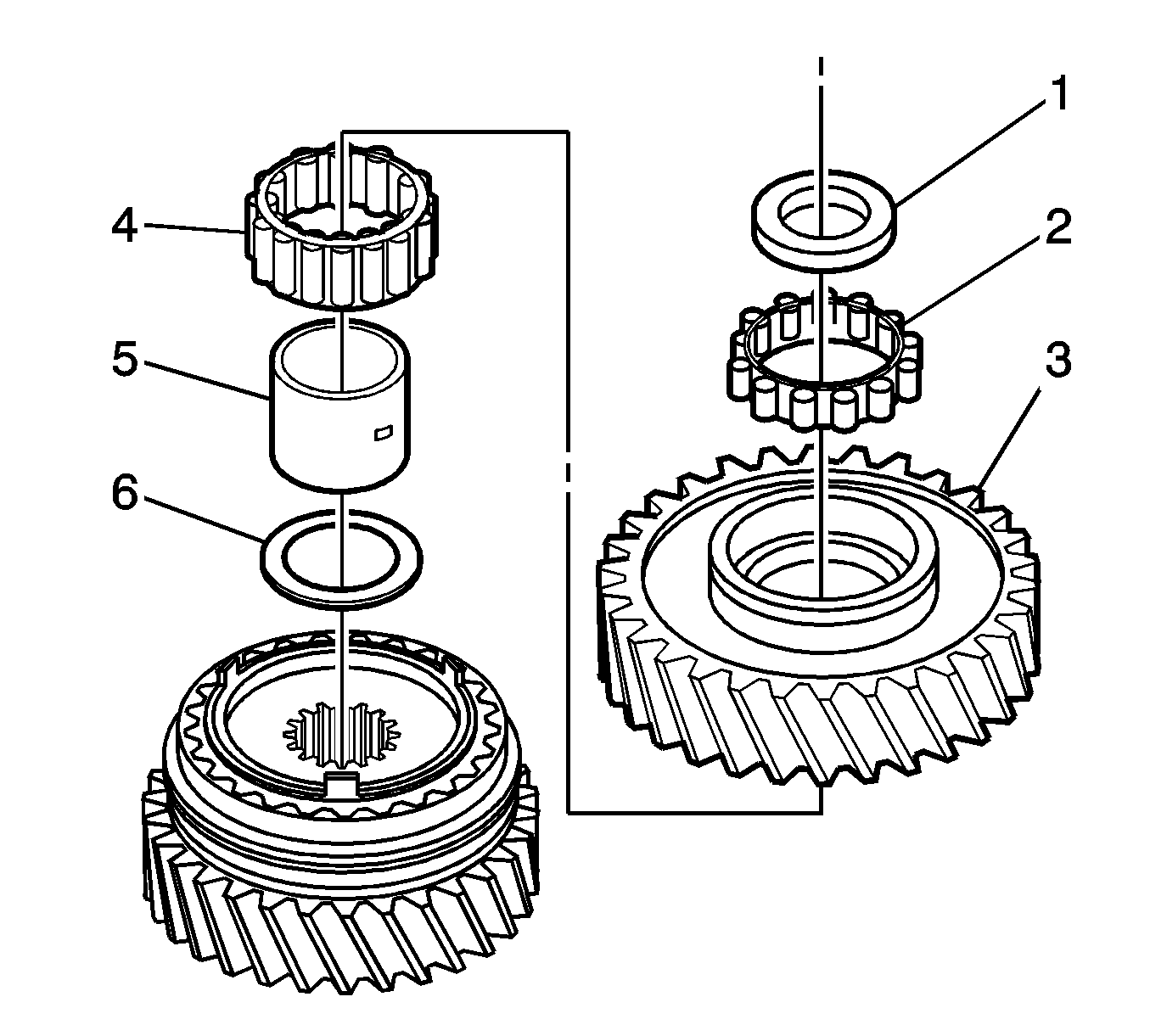
- Put the 1st gear assembly and the 2nd gear assembly, as a unit, on the bench.
- Remove the thrust washer (1).
- Remove the roller bearing (2).
- Remove the 1st gear (3).
- Remove the roller bearing (4).
- Remove the bearing collar (5).
- Remove the thrust washer (6).
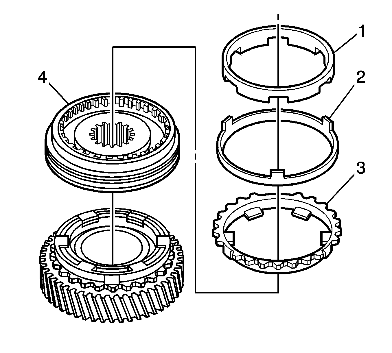
- Remove the 1st gear inner cone (1).
- Remove the 1st gear blocking ring (2).
- Remove the 1st gear outer cone (3).
- Remove the 1st/2nd synchronizer assembly (4).
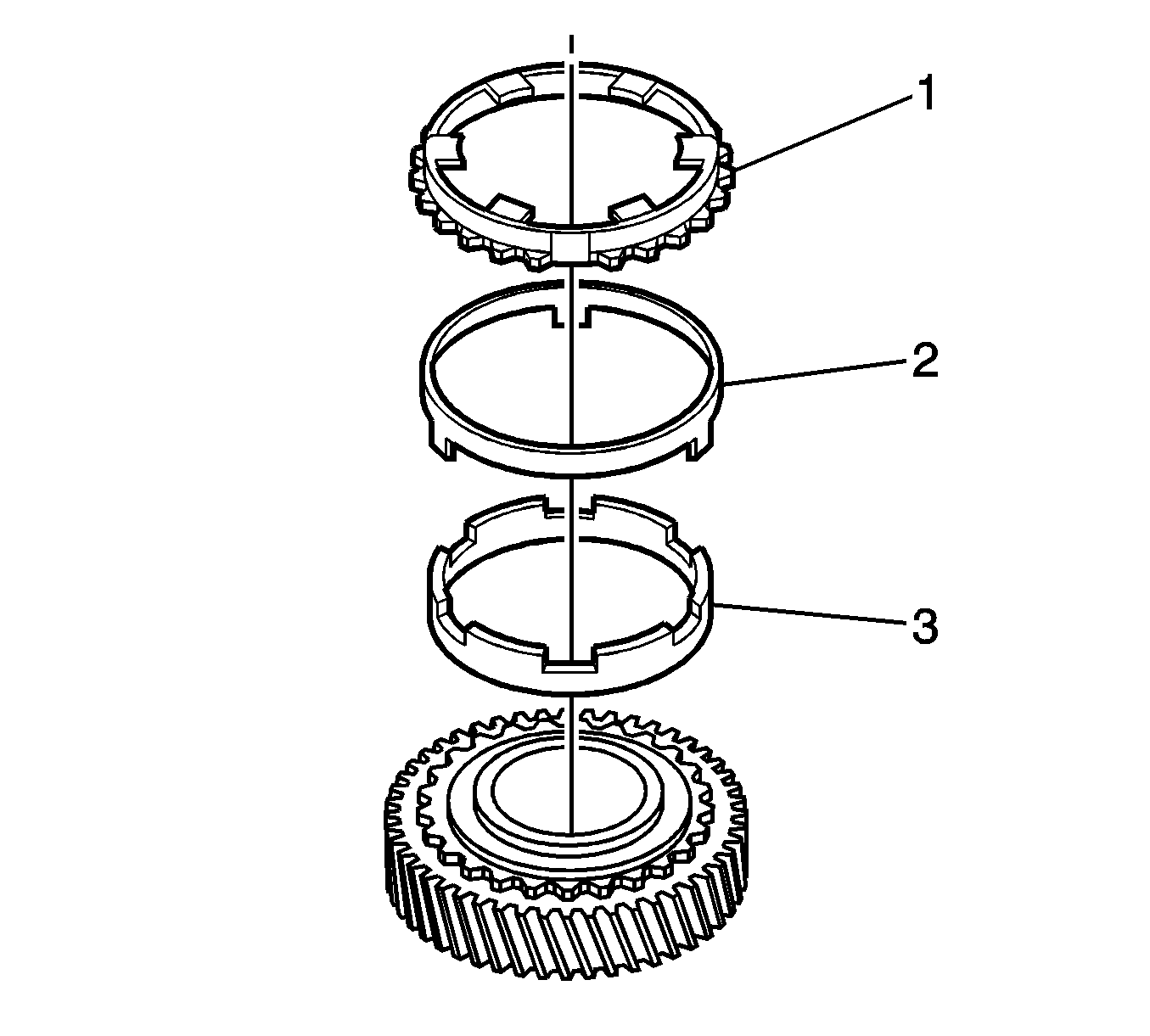
- Remove the 2nd gear outer cone (1).
- Remove the 2nd gear blocking ring (2).
- Remove the 2nd gear inner cone (3).
- Remove the 2nd gear.

- Remove the needle bearings from the interm shaft.
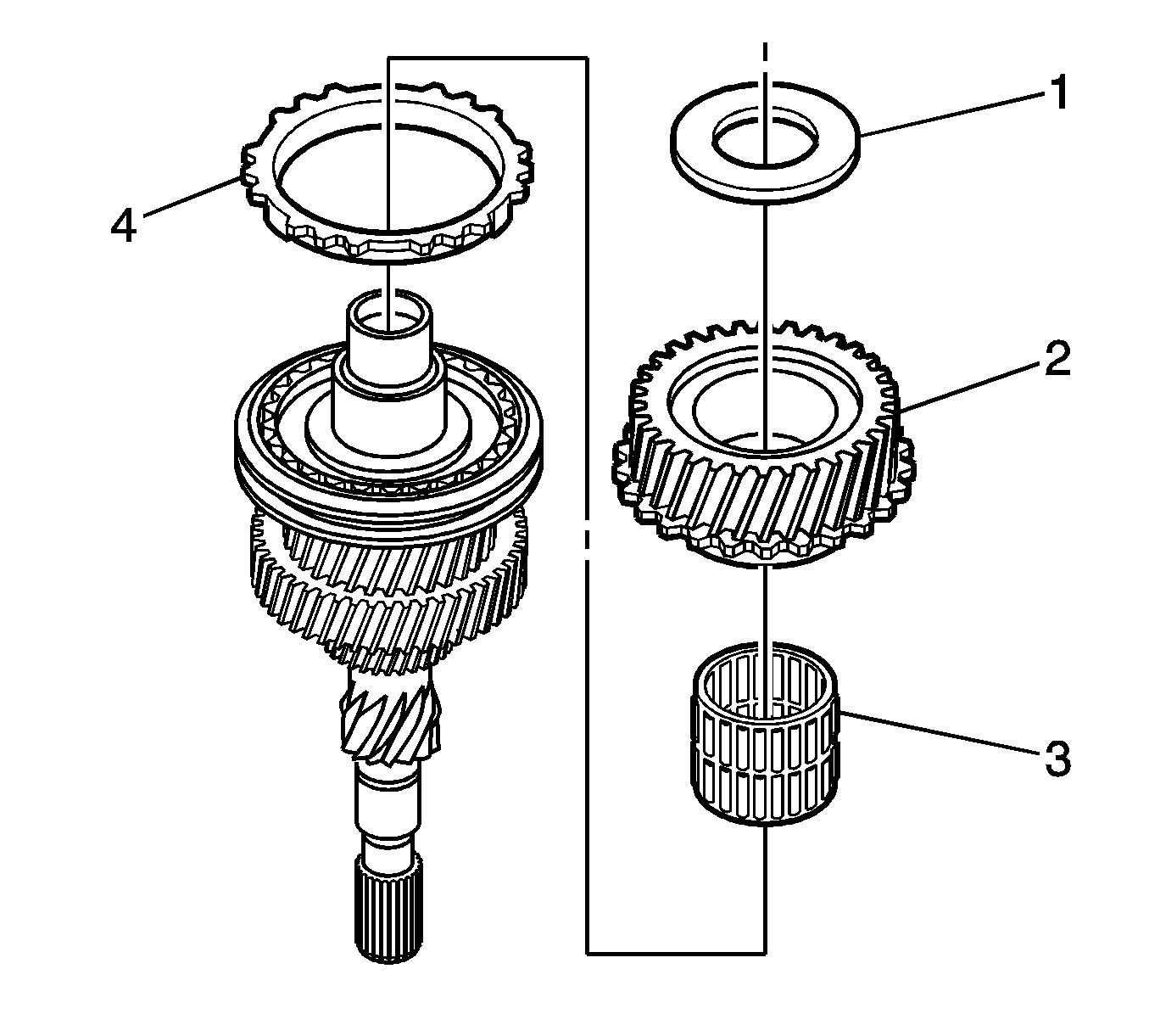
- Remove the thrust washer (1) from the input shaft.
- Remove the 4th gear (2).
- Remove the needle bearing (3).
- Remove the 4th gear blocking ring (4).
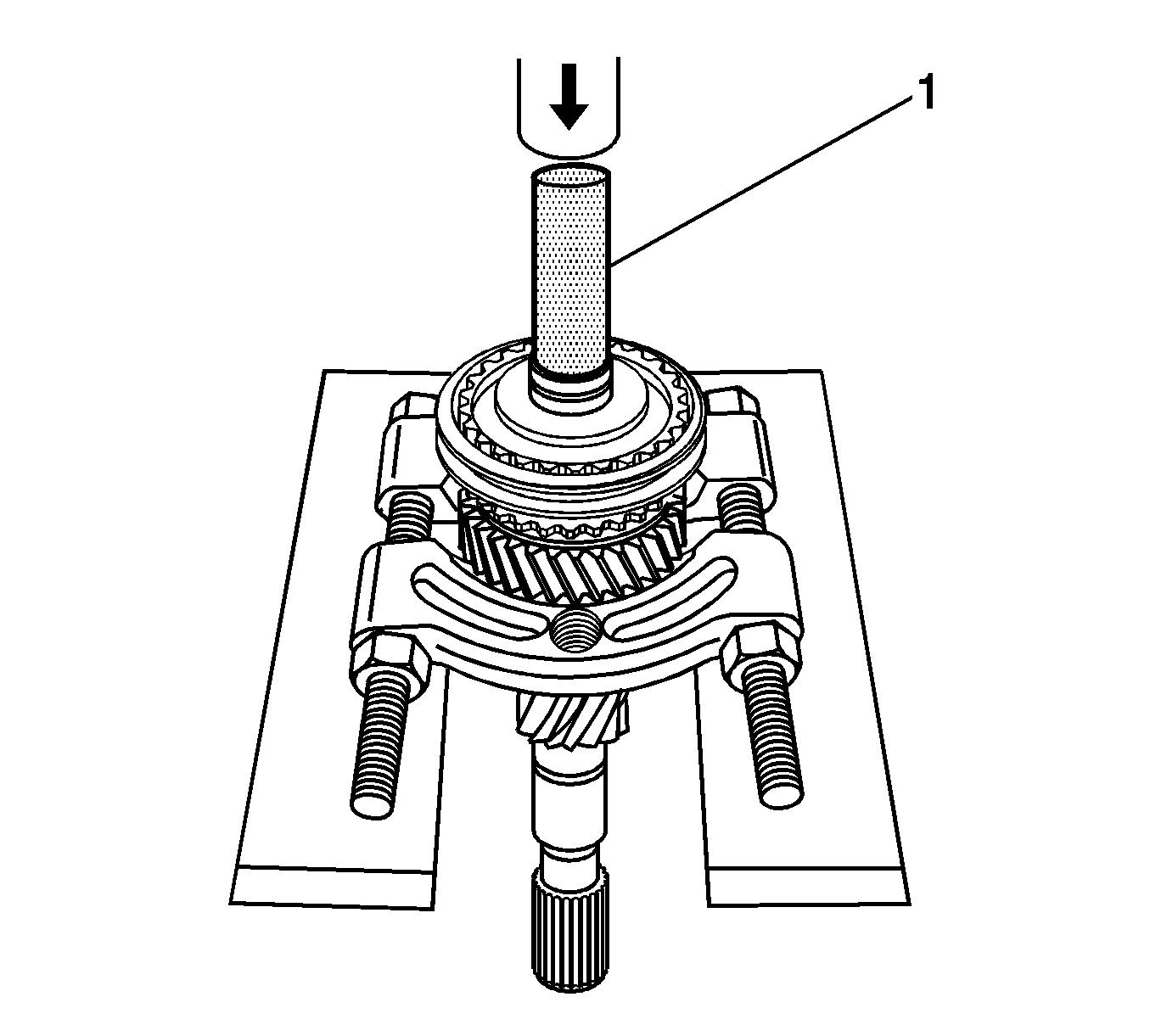
- Remove the bearing collar and the 3rd/4th synchronizer from the input shaft using the gear and bearing separator plate under the 3rd speed gear, the
DT-48192
(1) , and a hydraulic press.
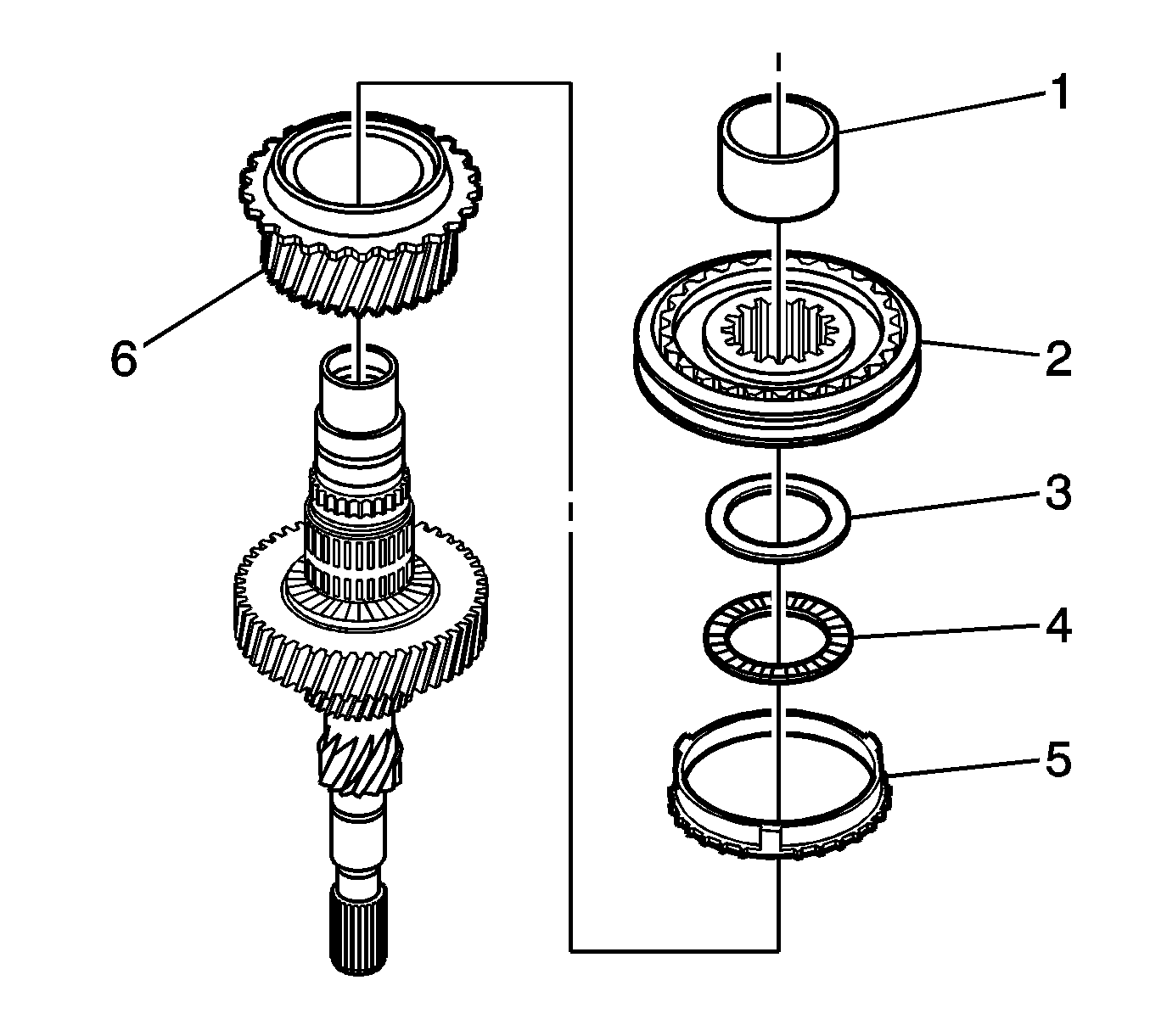
- Remove the following components as an assembly:
| • | The 3rd/4th synchronizer assembly (2) |
| • | The 3rd gear blocking ring (5) |

- Remove the needle bearing (1).
- Remove the thrust bearing (2).
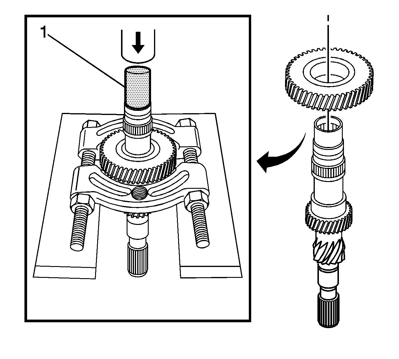
- Press off the 5th gear using the gear and bearing separator plate, the
DT-48192
(1) , and
a hydraulic press.
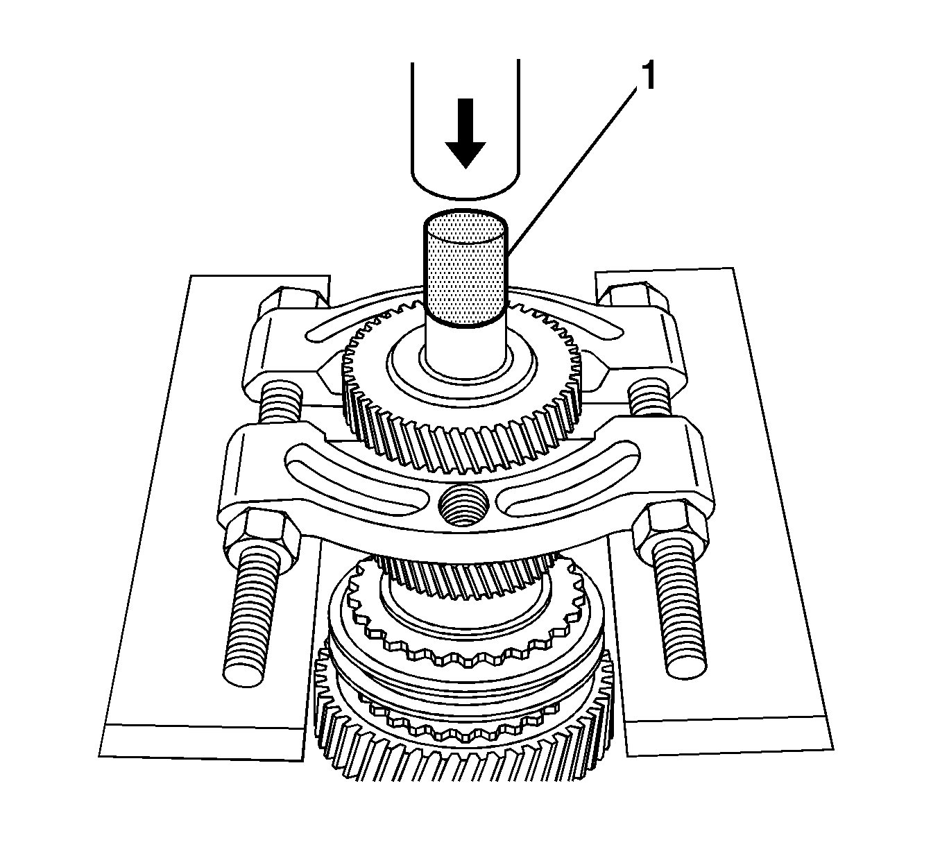
Note: The 4th driven gear is a very tight press.
- Press off the 4th driven gear from the output shaft using the gear and bearing separator plate, the
DT-48192
(1) , and a hydraulic press.
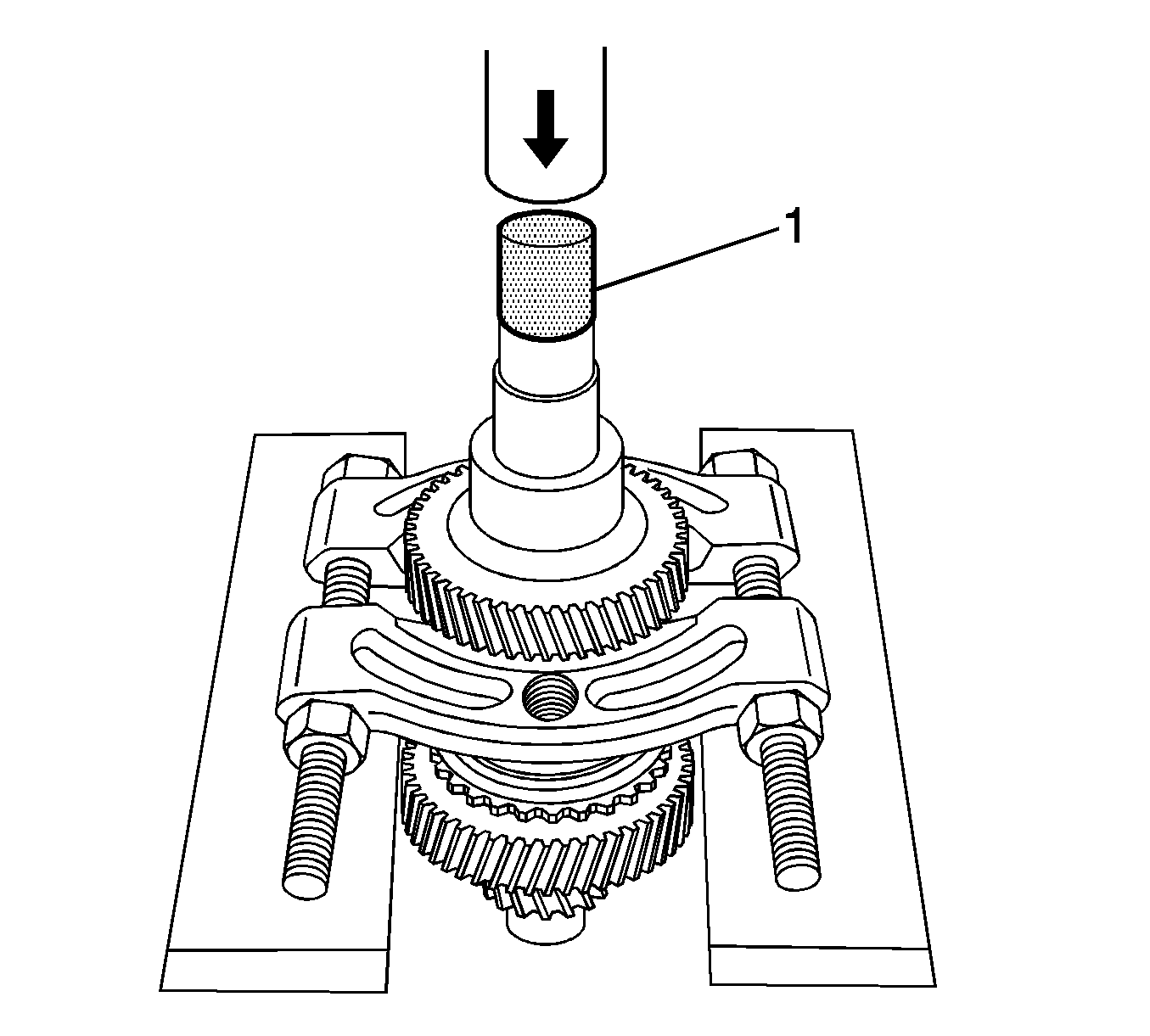
Note: The 3rd driven gear is a very tight press.
- Remove the 3rd driven gear using the gear and bearing separator plate, the
DT-48192
(1) , and a hydraulic press.
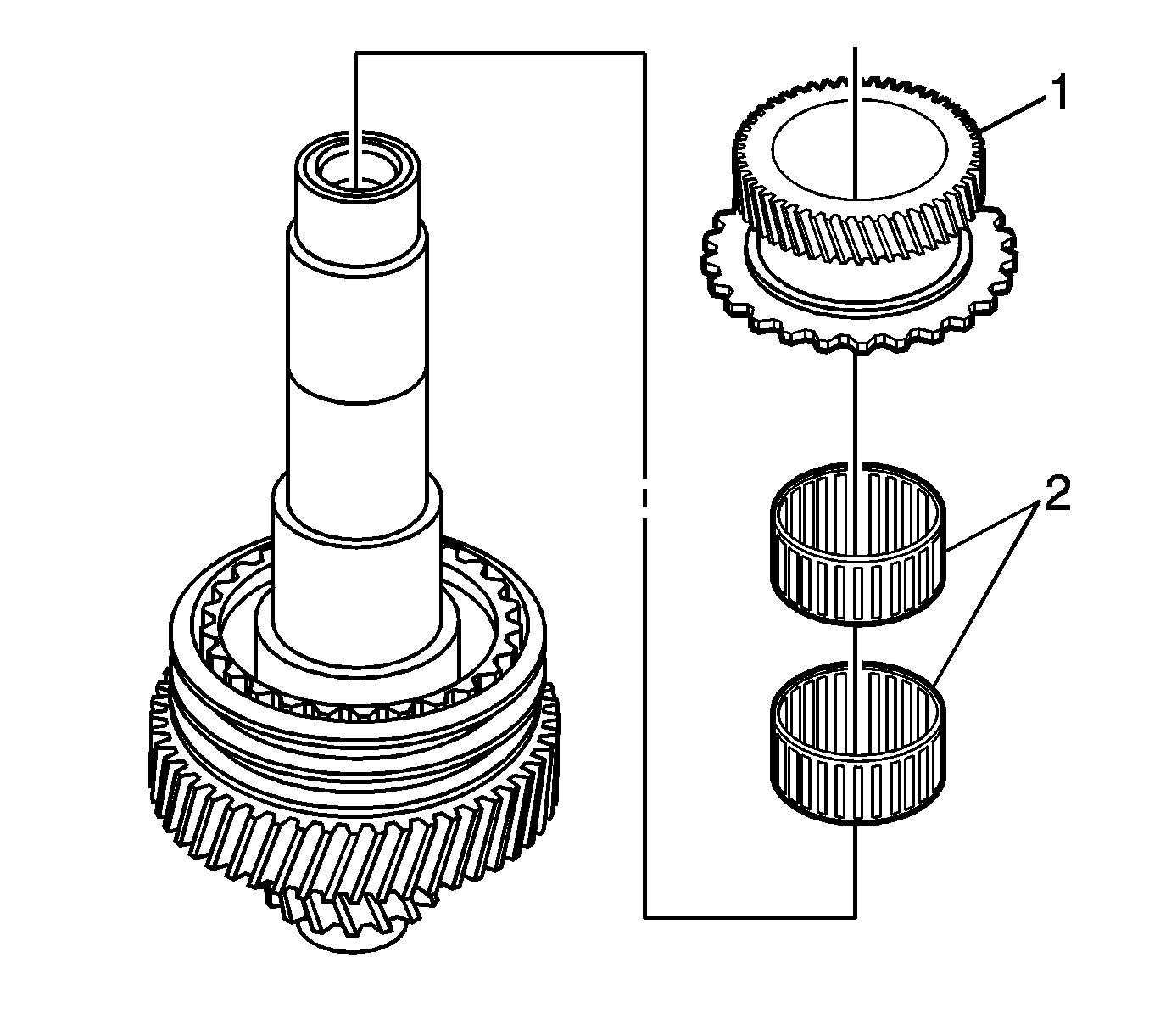
- Remove the 5th gear (1) and the 2 needle bearings (2).
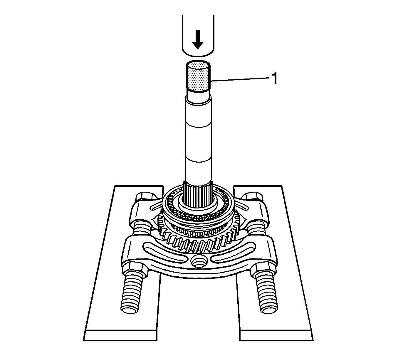
Note: Do not contact the thrust washer under the reverse gear.
- Remove the bearing collar using the gear and bearing separator plate, the
DT-48192
(1) , and a hydraulic press.
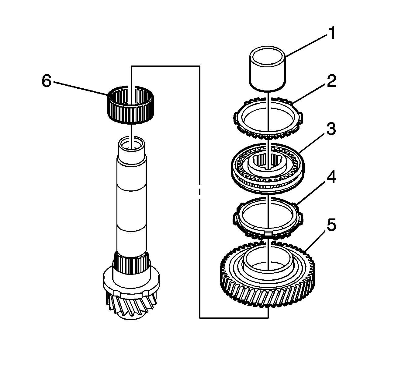
- Remove the following components as an assembly:
| • | The 5th gear blocking ring (2) |
| • | The 5th/Reverse synchronizer assembly (3) |
| • | The reverse blocking ring (4) |
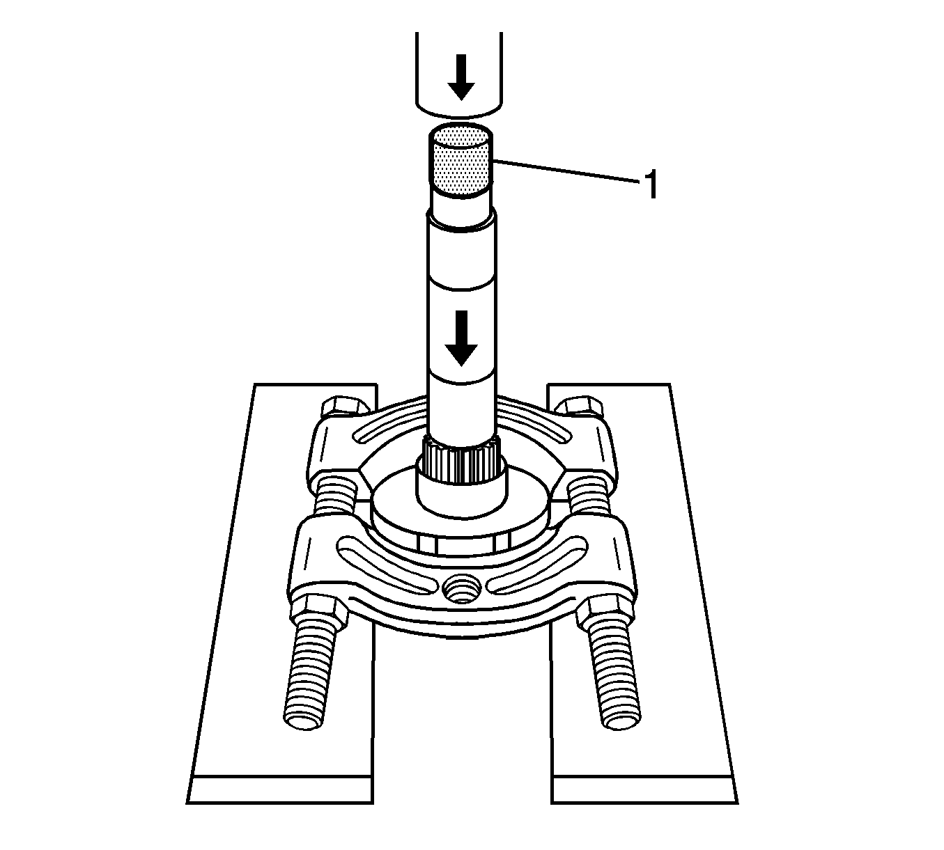
Note: Ensure that the gear and bearing separator plate is not making contact with the pinion gear before pressing off the collar and thrust washer.
- Remove the collar and the thrust washer using the gear and bearing separator plate, the
DT-48192
(1) , and a hydraulic press.
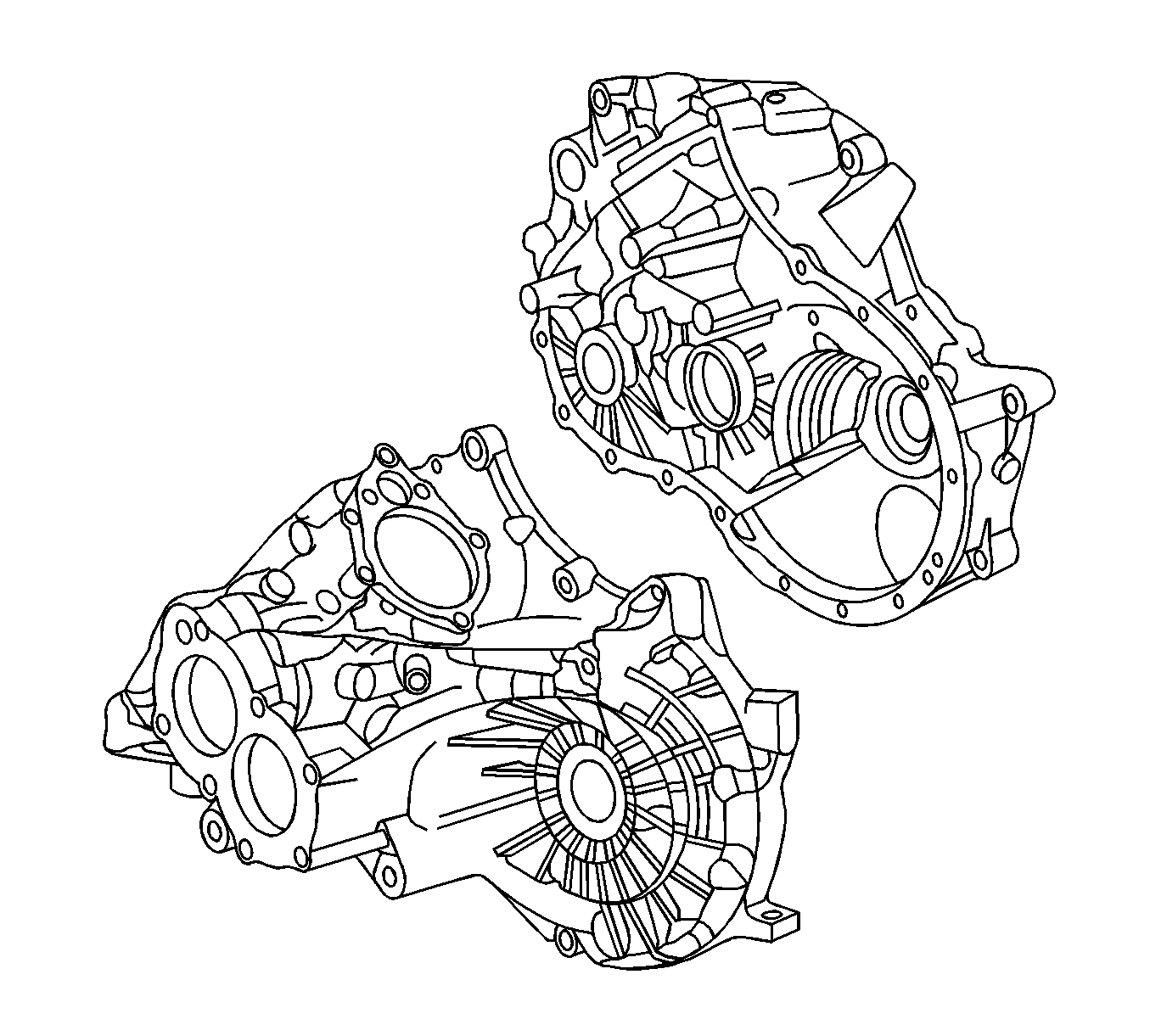
- Inspect the clutch housing and the differential housing and replace any part that exhibits any of the following conditions:
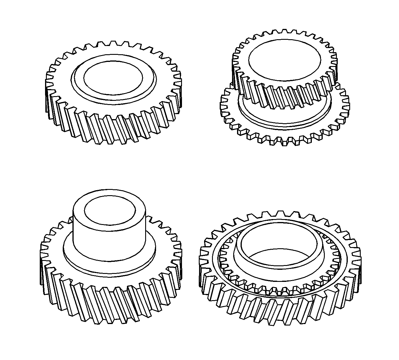
- Inspect the gear teeth and the gear splines for excessive wear or damage.
Remove minor nicks or scratches with an oil stone. Replace worn or
damaged gears.
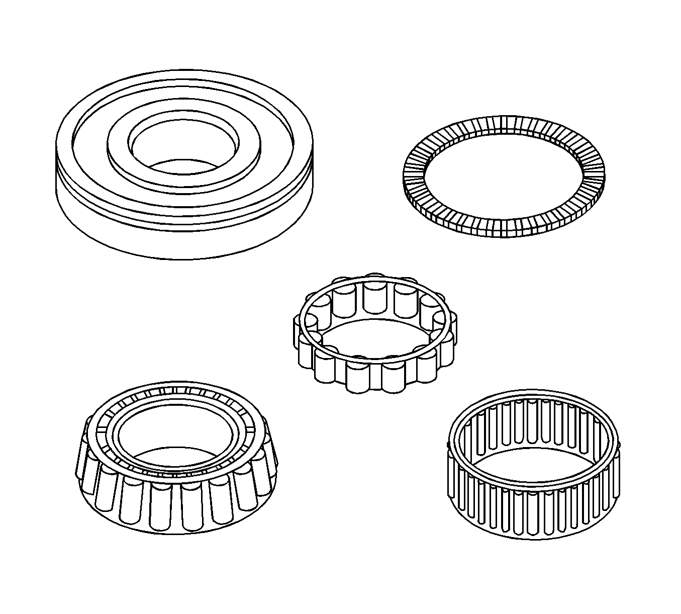
- Inspect the thrust washer for wear or damage. Replace worn or damaged thrust washers.
Note: Do not allow the bearings to spin. Turn the bearings slowly by hand. Spinning bearings may cause damage to the rollers.
- Inspect the condition of all thrust bearings, input shaft bearing, and output shaft bearing. Wash the bearings thoroughly in a cleaning solvent. Apply compressed air to the bearings. Lubricate the bearings with light oil. Check the bearings for roughness
by slowly turning the race by hand.

- Clean the synchronizer with clean solvent.
- Air dry the components.
- Inspect the synchronizer teeth for the following conditions. If any of the conditions exist, replace the synchronizer.
- Inspect the keys or the springs for the following conditions. If any of the conditions exist, replace the synchronizer.
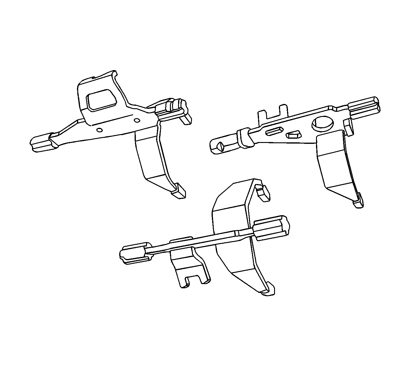
- Inspect the shift forks, shafts, and the rubber end for wear or damage. Replace any part that is worn or damaged.


