For 1990-2009 cars only
Removal Procedure
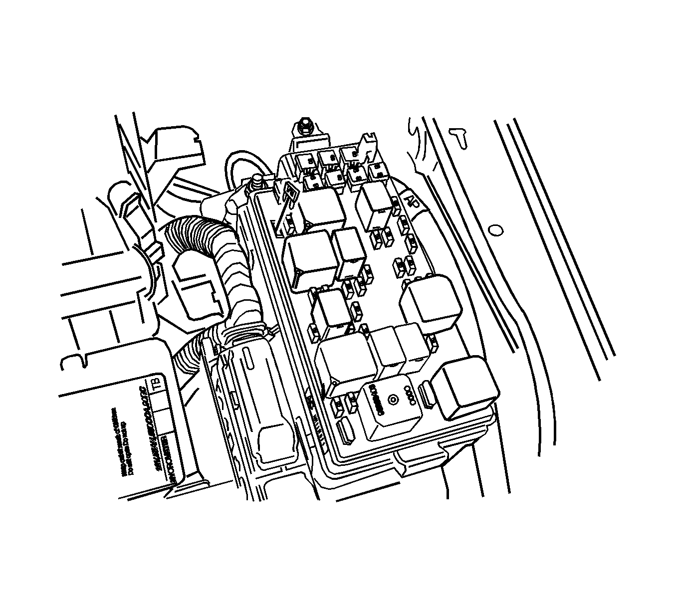
- Remove the fuel pump fuse.
- Start the engine and repeat cranking until the remaining fuel in the fuel line is all consumed.
- Disconnect the negative battery cable.
- Drain the engine coolant. Refer to Cooling System Draining and Filling.
- Drain the engine oil.
- Drain the transaxle oil.
- Drain the power steering oil.
- Recover the refrigerant. Refer to Refrigerant Recovery and Recharging.
- Remove the engine assembly. Refer to Engine Replacement.
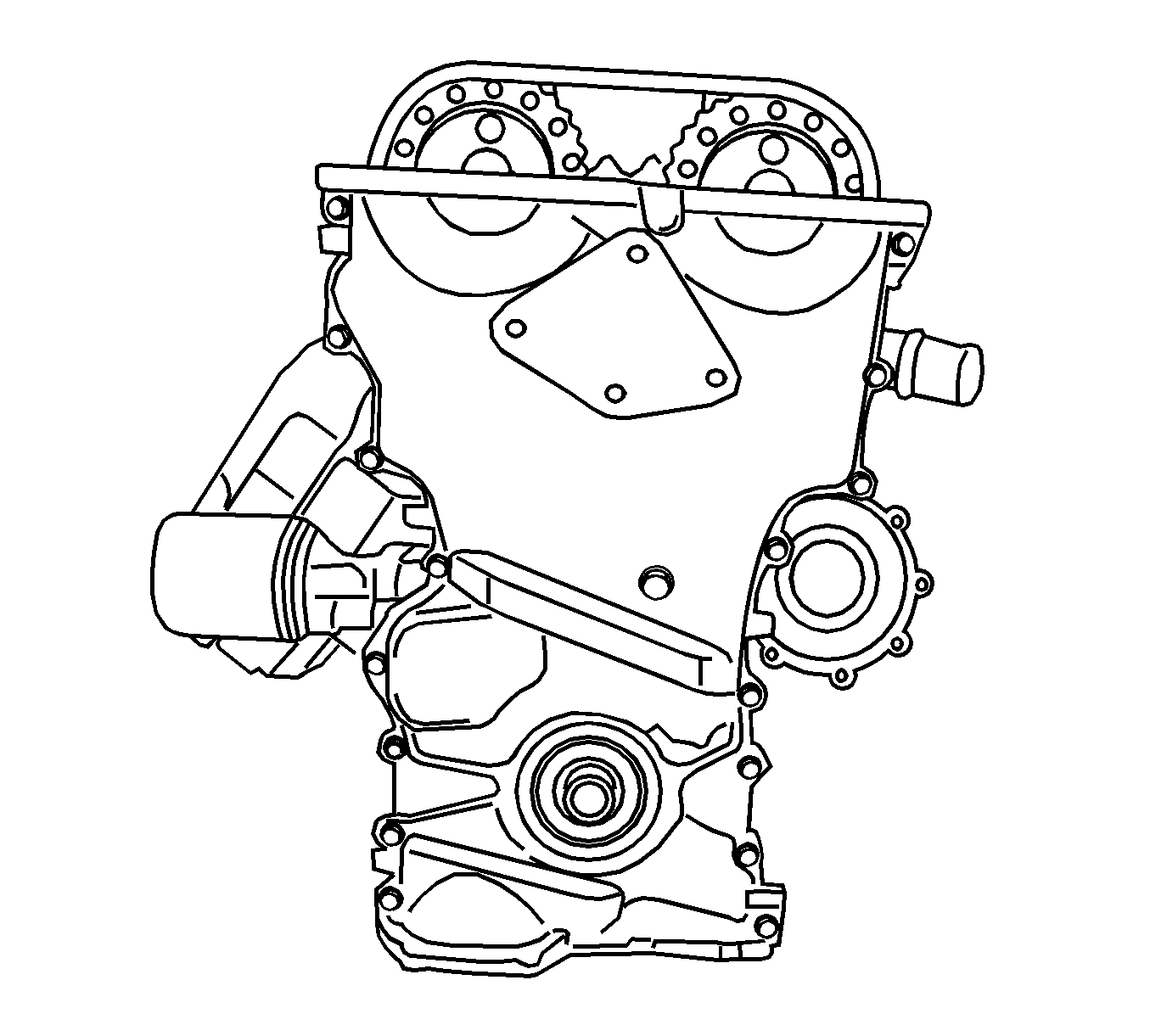
- Remove the timing chain cover. Refer to Camshaft Timing Chain and Sprocket Replacement.
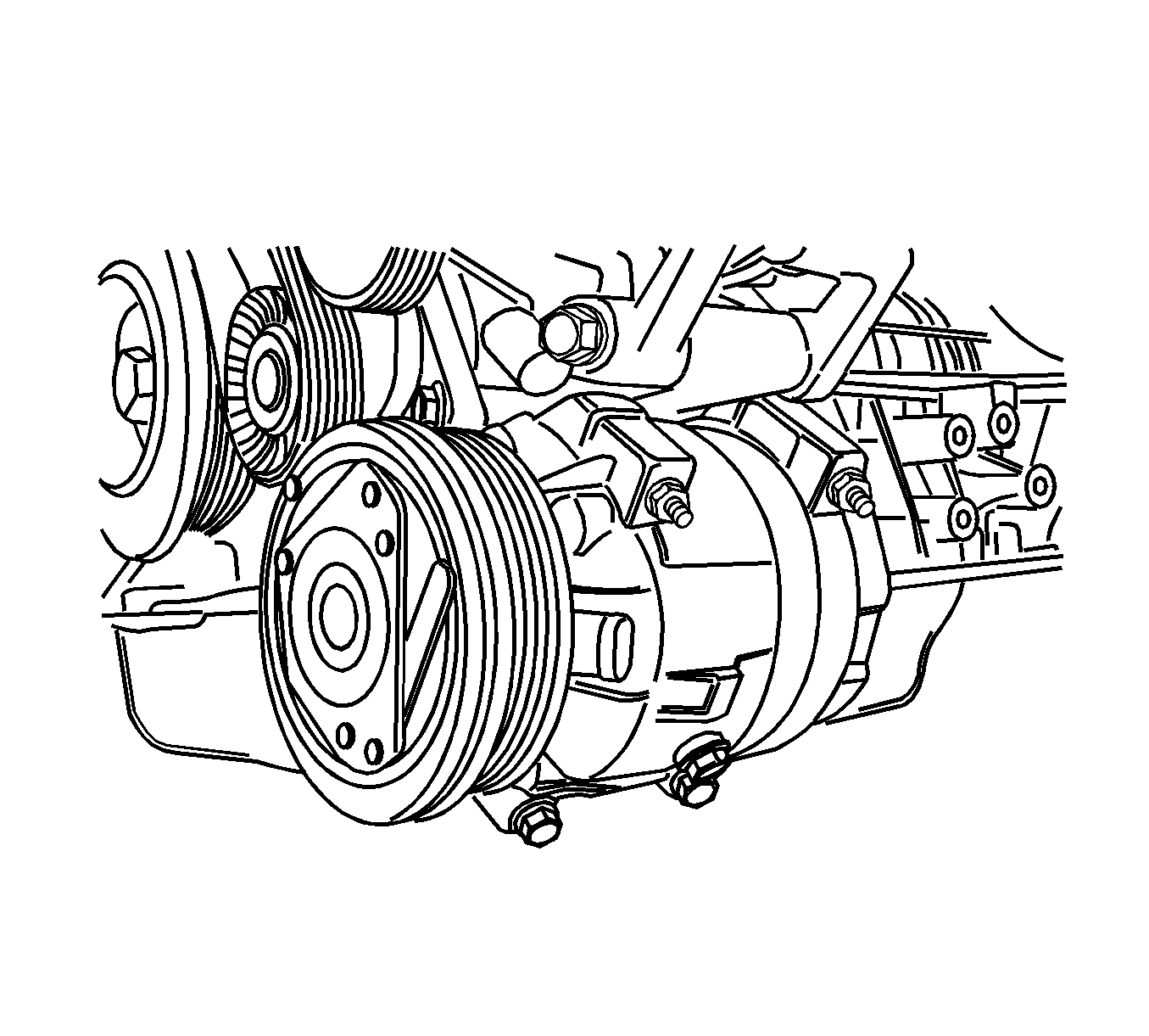
- Remove the compressor.
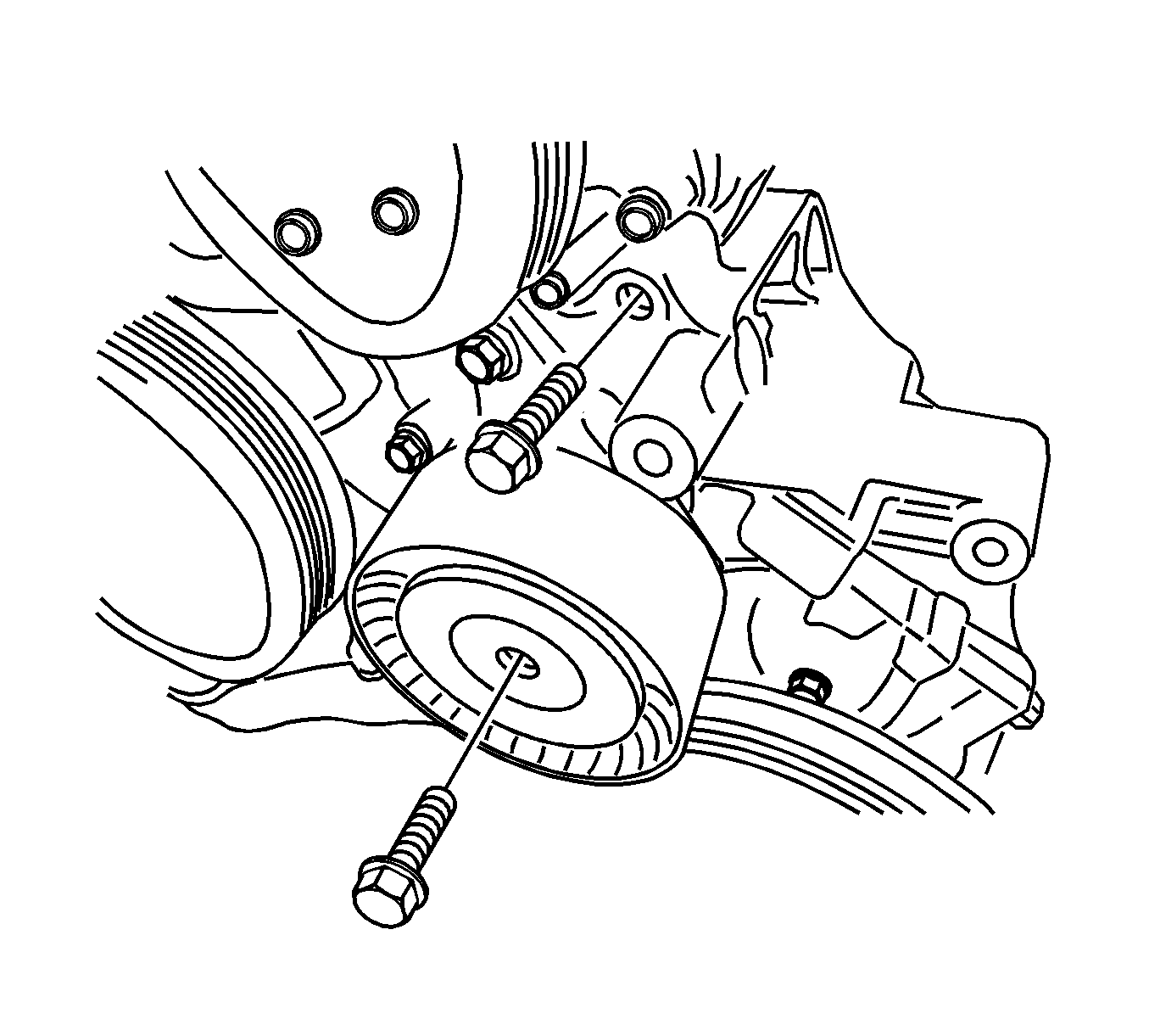
- Remove the idler retaining bolt, upper pad-to-lower pad bracket bolt, and the idler.
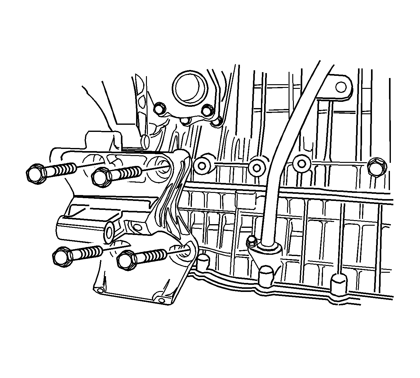
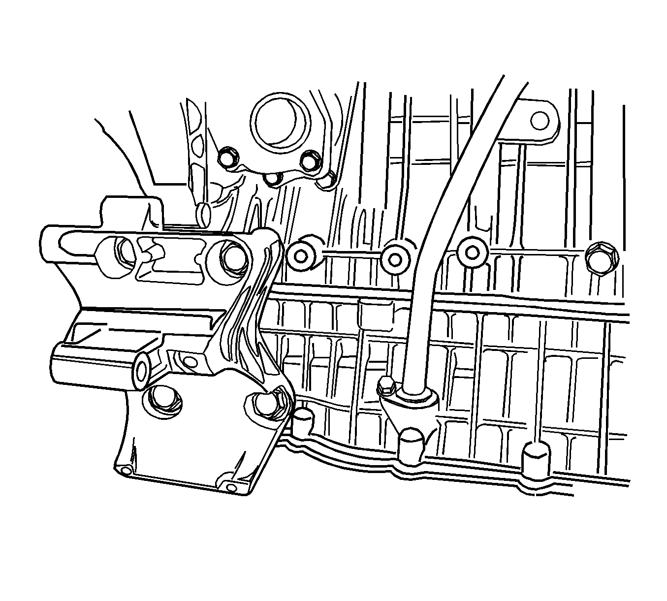
- Remove the lower pad bracket.
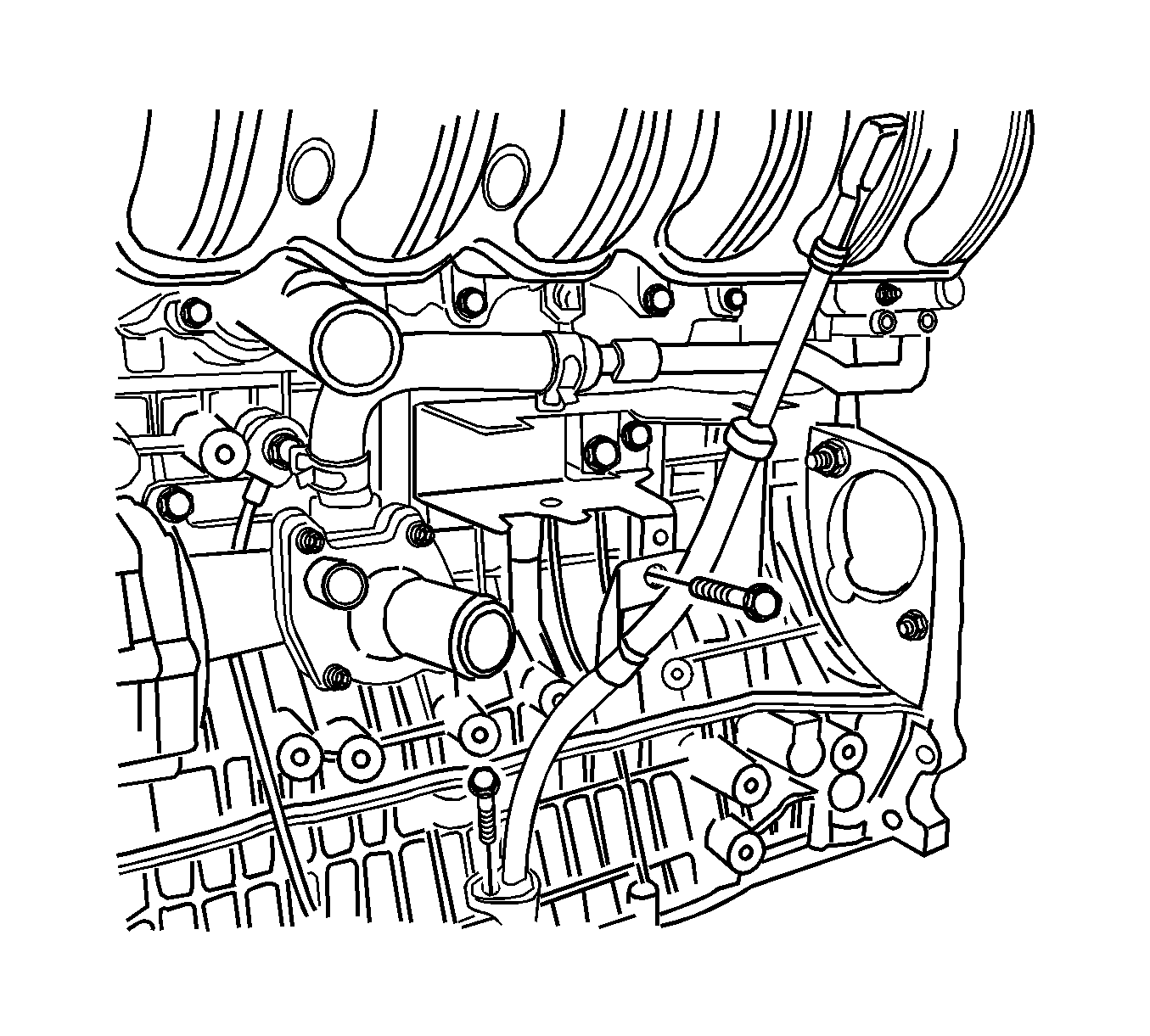
- Remove the engine oil dipstick tube.
- Remove the crankshaft position (CKP) sensor. Refer to Crankshaft Position Sensor Replacement.
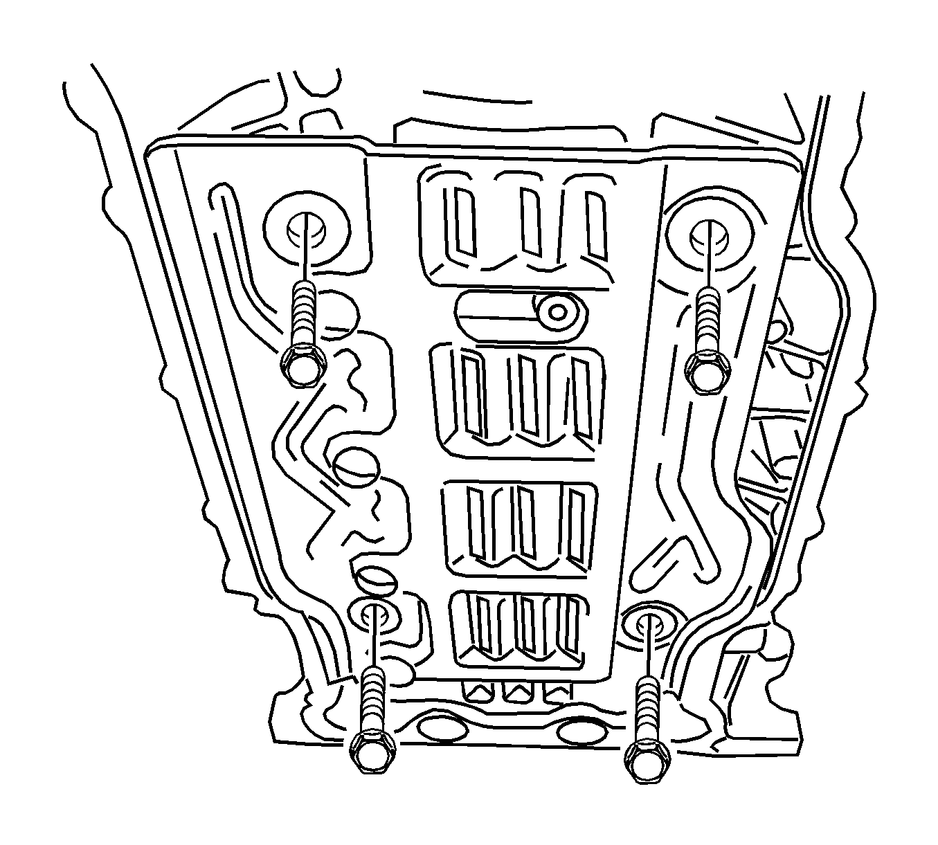
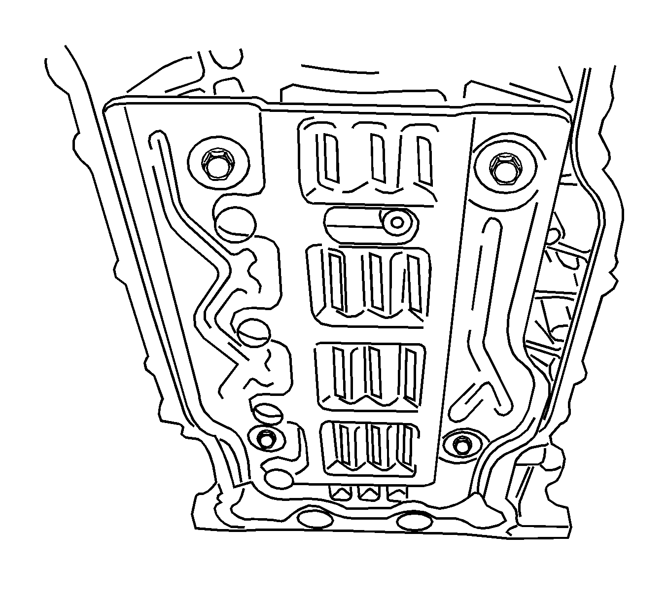
- Remove the bed plate baffle.
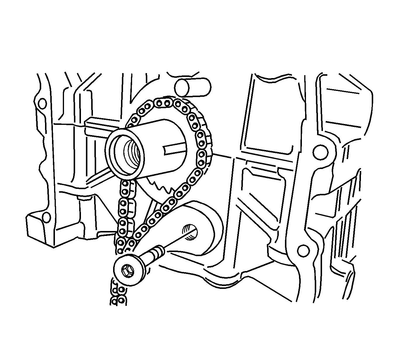
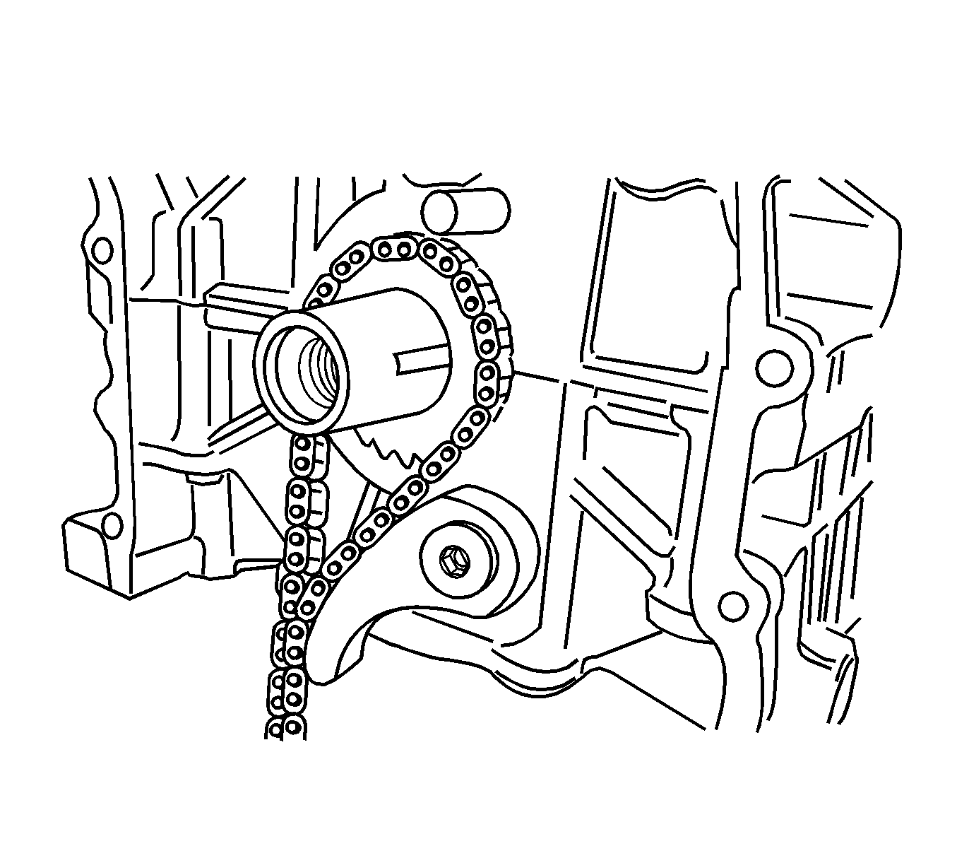
- Remove the oil pump chain lever.
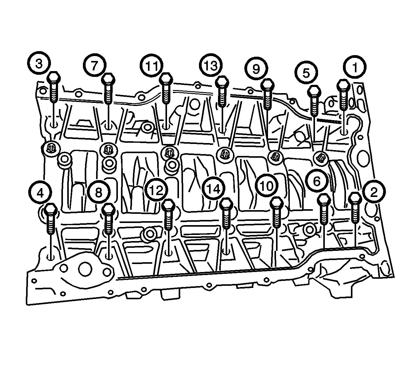
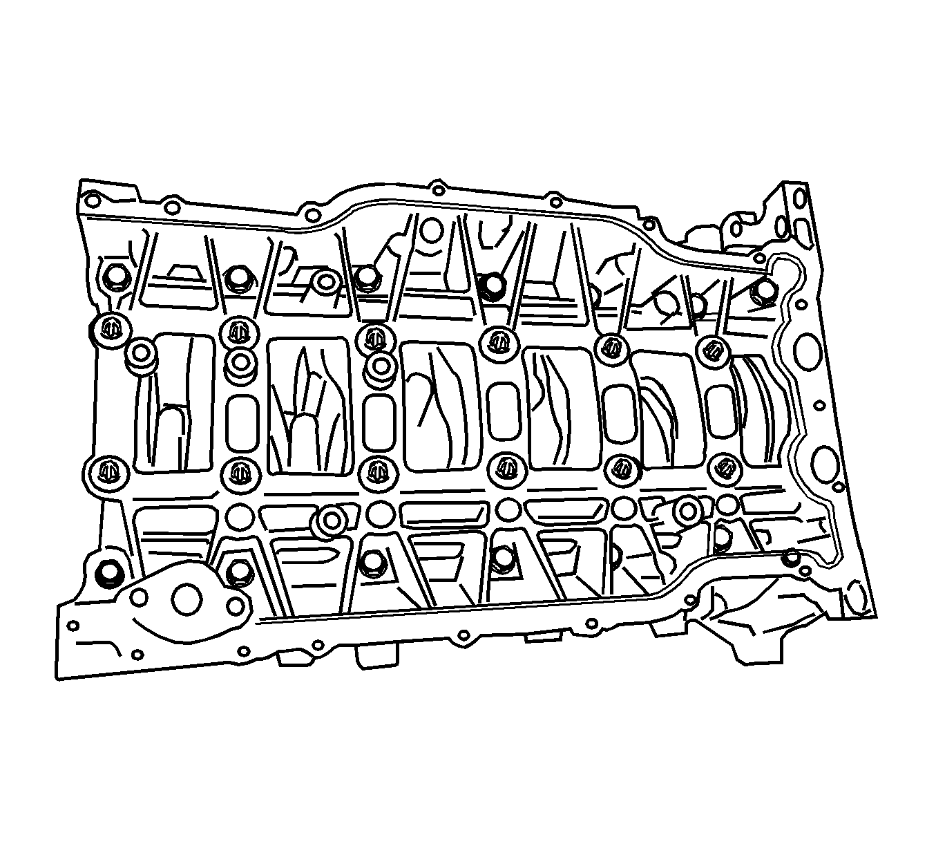
- Remove the bed plate outer bolts in the sequence shown.
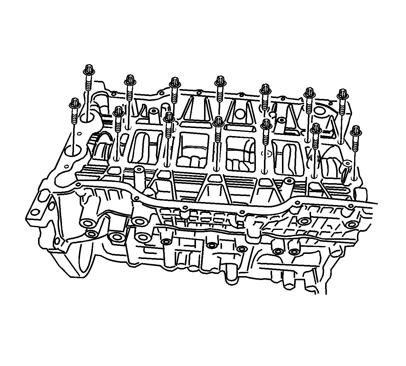
- Remove the bed plate inner bolts.
Warning: Refer to Battery Disconnect Warning in the Preface section.
Installation Procedure
- Clean the contact surfaces between the bed plate and the cylinder block.
- Apply the liquid gasket, Loctite® 5900-M8585, on the bed plate.
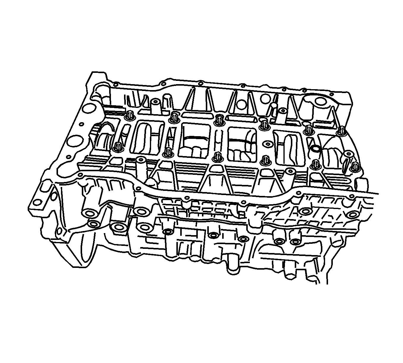
- Install the bed plate and tighten the inner bolts to 33 N·m (24 lb ft). After tightening all the inner bolts, turn the bolts by 135 degrees each.
- Tighten the bed plate outer bolts to 20-26 N·m (15-19 lb ft).
- Install the oil pump. Refer to Oil Pump Replacement.
- Install the oil pump chain lever and tighten the bolt to 8 N·m (71 lb in).
- Install the bed plate baffle and tighten the bolts to 8 N·m (71 lb in).
- Install the oil pan. Refer to Oil Pan Replacement.
- Install the engine oil dipstick tube.
- Install the CKP sensor. Refer to Crankshaft Position Sensor Replacement.
- Install the lower pad bracket and tighten the bolts to 40 N·m (30 lb ft).
- Install the idler.
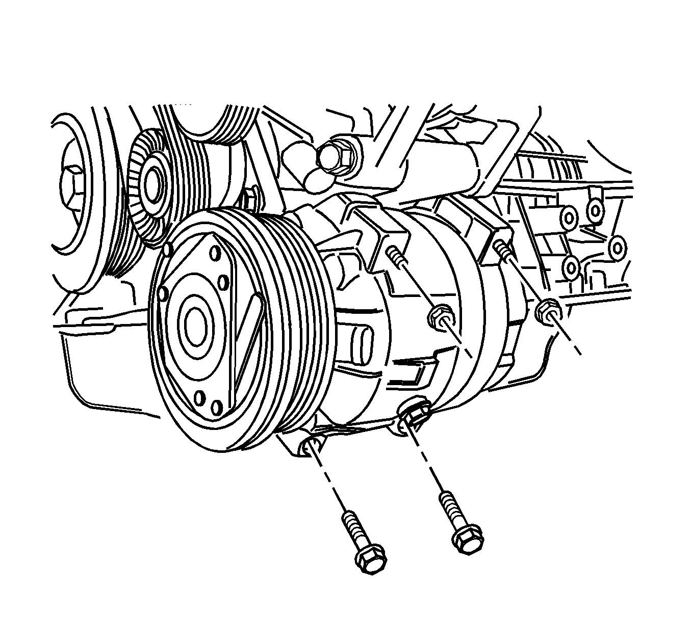
- Install the compressor and tighten the retaining bolts and nuts to 25 N·m (18 lb ft).
- Install the timing chain and timing chain cover. Refer to Camshaft Timing Chain and Sprocket Replacement.
- Install the engine assembly. Refer to Engine Replacement.
- Install the fuel pump fuse.
- Connect the negative battery cable.
- Refill the crankcase with engine oil.
- Refill the engine coolant system. Refer to Cooling System Draining and Filling.
- Fill and bleed the power steering system. Refer to Power Steering System Bleeding.
- Refill the A/C System. Refer to Refrigerant Recovery and Recharging.
Caution: Refer to Fastener Caution in the Preface section.
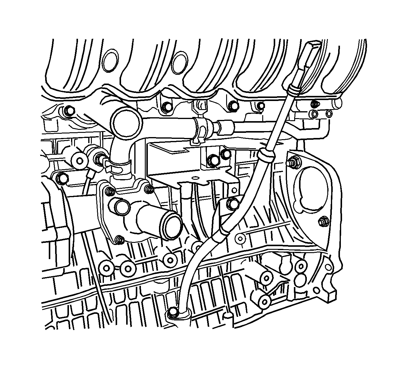
| • | Tighten the engine oil dipstick tube bracket bolt to 20 N·m (15 lb ft). |
| • | Tighten the engine oil dipstick tube bolt to 9 N·m (80 lb in). |
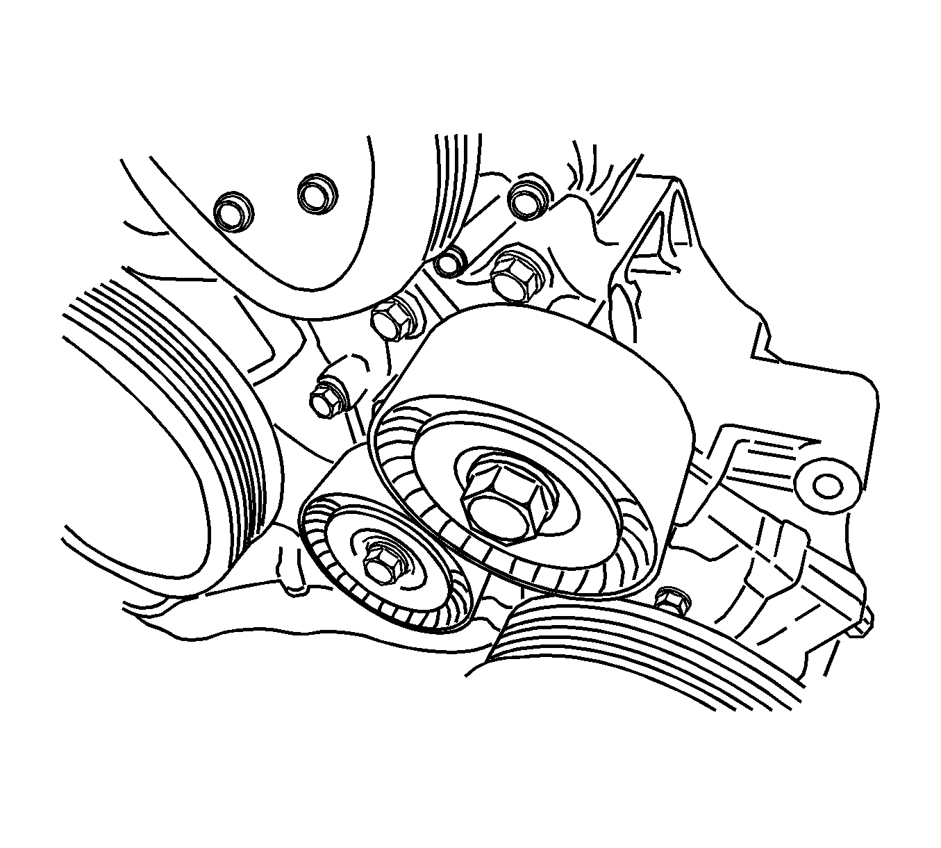
| • | Tighten the idler retaining bolts to 45 N·m (33 lb ft). |
| • | Tighten the upper pad-to-lower pad bracket bolt to 35 N·m (26 lb ft). |
