Special Tools
J 41229 Manual Shaft Pin Installer
Removal Procedure
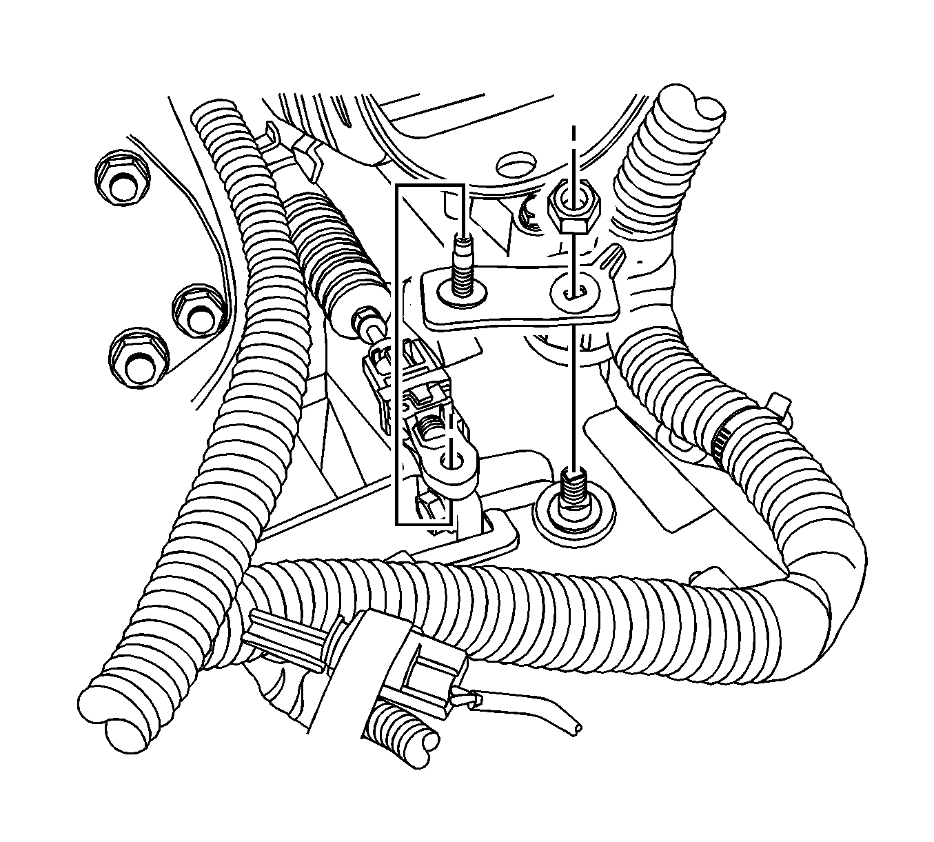
- Remove the A/T range selector lever. Refer to Automatic Transmission Range Selector Lever Replacement.
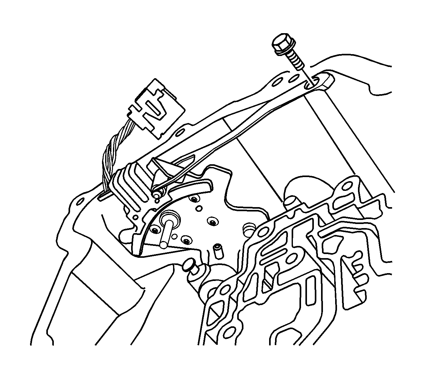
- Remove the control valve body assembly. Refer to Control Valve Body Replacement.
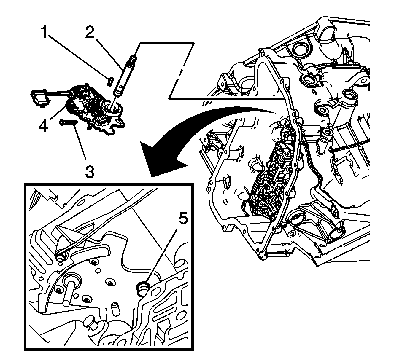
- Remove the manual shaft detent lever spring assembly and bolt.
- Remove the manual shift shaft pin (2) with a small nail puller.
- Remove the manual shaft detent lever hub pin (1) using a pry bar and pliers.
- Remove the manual shaft (3).
- Remove the manual shift detent lever assembly (4) from the transmission case after disconnecting it from the actuator assembly (5) carefully.


Note: Discard the pin. It is not reusable.
Note: Do not pull the park actuator rod end out beyond the machined oil passage surface in the case. A no park condition will exist if the park pawl actuator assembly is pulled out of the transmission too far and the actuator rod disengages from the park pawl.
Installation Procedure
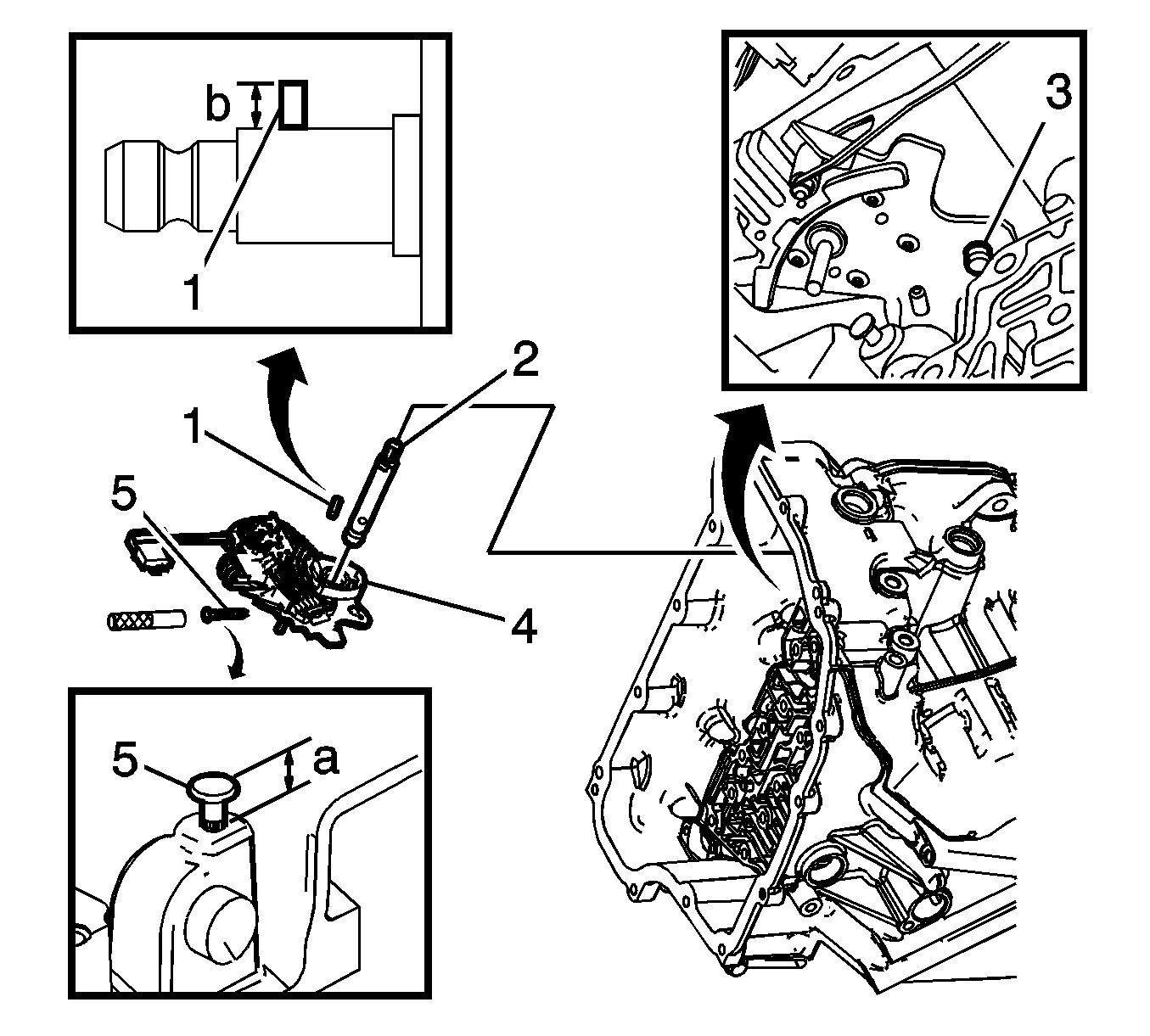
- Connect the manual shaft detent lever assembly (2) to the actuator assembly (1) and install it in the case.
- Install the manual shaft (3).
- Install the manual shaft detent lever hub pin (4).
- Install the manual shift shaft pin (5).
- Install the manual shaft detent lever spring assembly and bolt and tighten to 12 N·m (106 lb in).
- Rotate the switch to check that the switch is installed correctly.
- Install the control valve body assembly. Refer to Control Valve Body Replacement.
- Install the A/T range selector lever. Refer to Automatic Transmission Range Selector Lever Replacement.

Note: Lubricate the shaft with ATF to prevent damage to the manual shift shaft seal during installation.
Specification
Install the manual shaft detent lever hub pin to height of (b) 7.9 mm (0.38 in).
Note: Use J 41229 to install the manual shift shaft pin at the correct height in order to properly secure the manual shaft. If you install the pin too deep, the case bore may crack.
Note: Use a new pin to ensure proper engagement with the case. Inspect manual shift shaft pin installed height (a) is within 7.2-8.2 mm (0.28-0.32 in).
Caution: Refer to Fastener Caution in the Preface section.


