Except for some specific connector bodies, wiring harness terminals, terminal seals and connector bodies are generally not serviced individually.
Specific terminals, with seals (if fitted) are serviced only as an assembly with a wiring pigtail attached. Refer to Parts Information for a listing of serviced terminals and connector bodies.
When conducting wiring harness repairs that involve replacement of damaged terminal(s), remove the terminal(s) from the connector body (refer to instructions in this Volume) and splice new terminal(s) with wiring pigtail into the wiring harness (refer to instructions in this Volume).
If a specific wiring harness terminal or connector body is damaged beyond repair, and the terminal or connector body is not serviced, the wiring harness must be replaced.
Performing Wiring Harness Repairs
Notice: Special wiring repair procedures have been developed for use on the ABS and SRS due to the sensitive nature of their circuitry. The procedures in SIR/SRS Wiring Repairs are the only recommended and approved ABS and SRS wiring repair methods. The following wiring repair methods are not to be used on ABS or SRS wiring.
Soldering
With electrical wiring only resin flux can be used. Acid flux creates a corrosion condition that makes it unsuitable for this work.
Do not clean resin flux off after soldering as the resin acts as an anti-corrosive to protect the soldered area.
The five points upon which an electrical soldering joint is judged are as follows:
- Soldering Preparation:
- Iron Preparation:
- Form a Heat Bridge:
- Soldering Iron Removal:
- Prevent Job Movement:
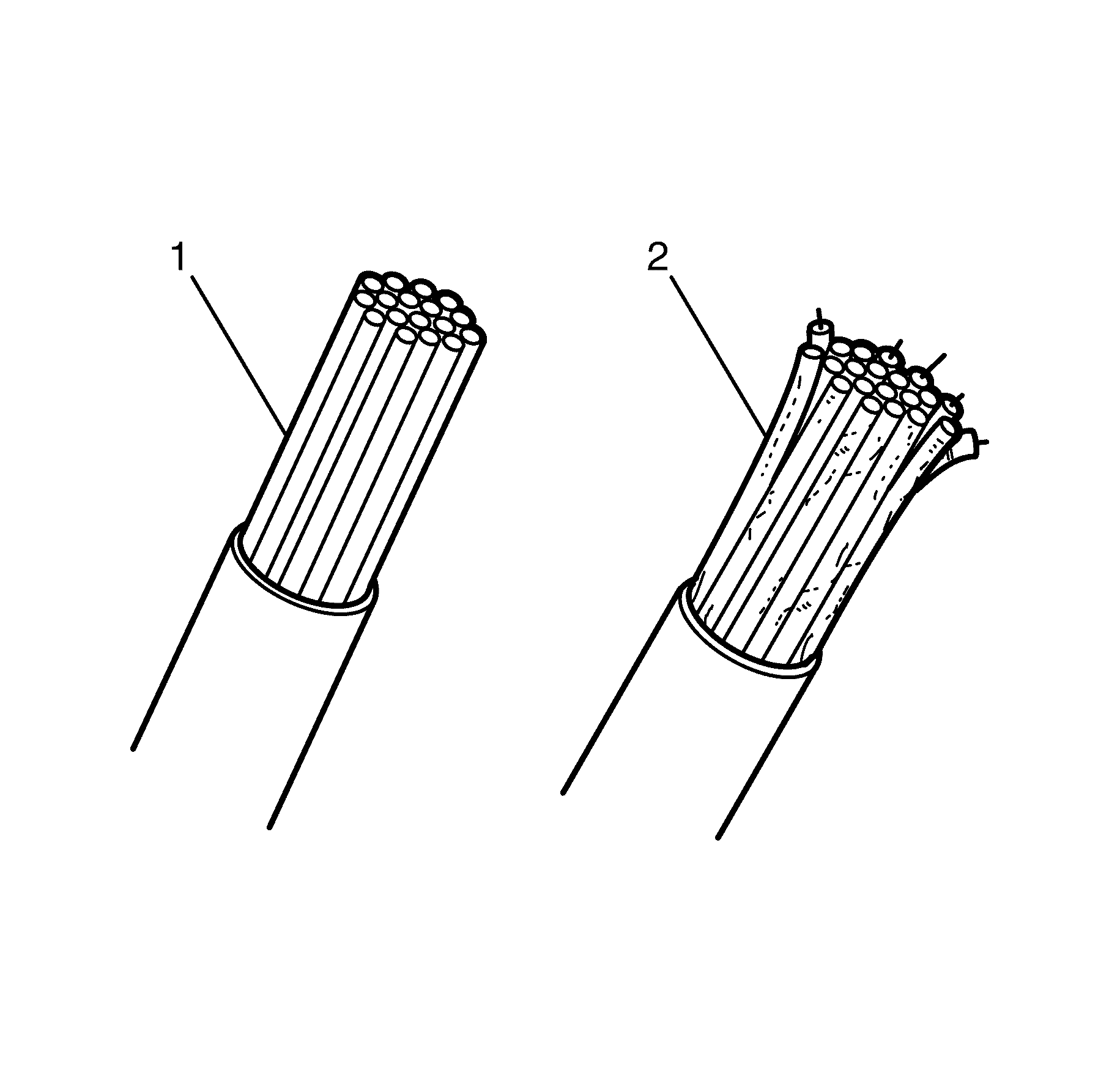
The job must be clean (1). Corroded and/or greasy wiring ends (2) should be stripped back.
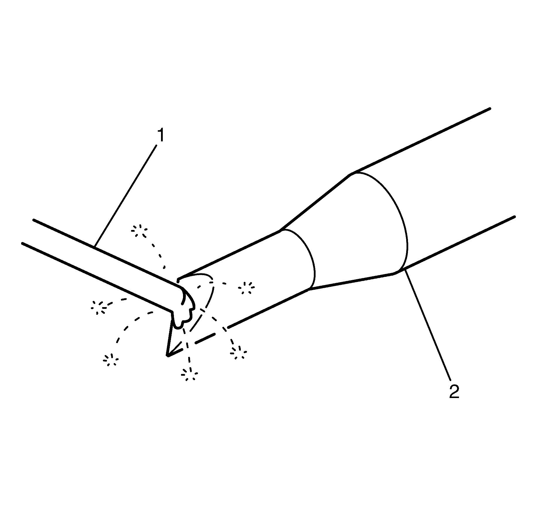
| • | The soldering iron (2) must be tinned and hot before application. Preheat the soldering iron (2) to slightly above solder melting point before applying solder (1) or applying it to the job to allow for heat loss on contact. |
| • | The commencement of "flux spit" is an indication of correct preheat temperature. |
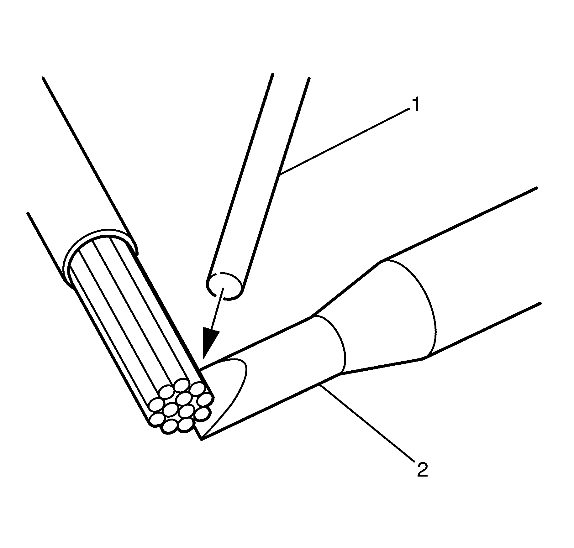
| • | Apply the full face of the soldering iron (2) to the job and immediately add solder (1) to the "V" formed by the iron and the job. |
| • | This is known as heat bridge where the melting solder speeds up the heat transfer and cuts down the job heating time. |
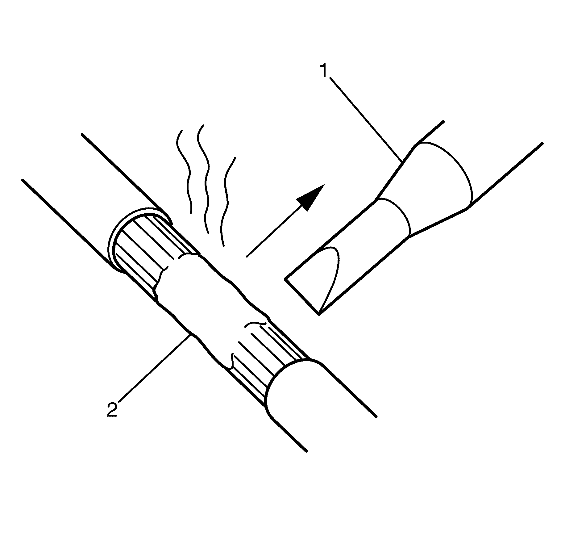
Remove the soldering iron (1) the instant the job is complete. This prevents the solder (2) travelling outside the intended deposit area.
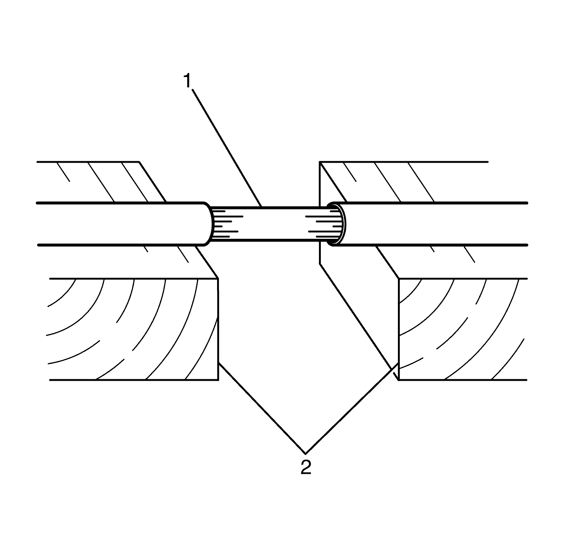
| • | Prevent job movement until the solder cools. |
| • | A soldered joint (1) can be weakened if the two components being joined move in relation to each other just as the liquid solder changes to a solid state. |
| • | Making a second attempt to solder the joint is undesirable as prolonged heating is necessary to remelt the solder. |
| • | Arrange support (2) before you start and use it until the solder cools. |
Joining Wire
Twist Joint
The twist joint is simple and strong.
- Strip 20 mm (0.8 in) of insulation from each wire (1).
- Twist the strands to compact them.
- Join them together by twisting (2).
- Complete the join by soldering.
- Use PVC tape to insulate the joint.
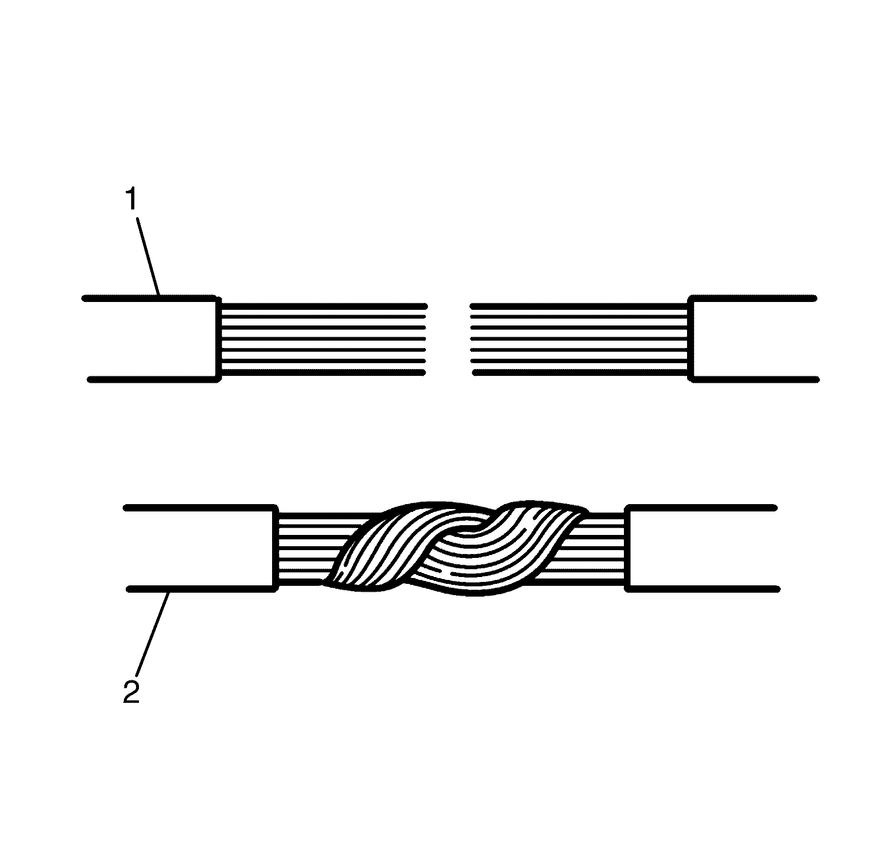
Important: To prevent a short or grounded circuit, remove all the "spikes" from the join before insulating. Spikes can be formed by wire strands or solder itself. These can cut through the insulation.
Splice Joint
Important: A good splice may be a little harder to achieve but it makes a neater join that is less bulky when taped.
To splice join conductors:
- Strip back 20 mm (0.8 in) of insulation and spread the strands (1).
- Push the strands together and twist the ends in opposite directions to compact the joint (2).
- Solder the joint.
- Use PVC tape to insulate the joint.
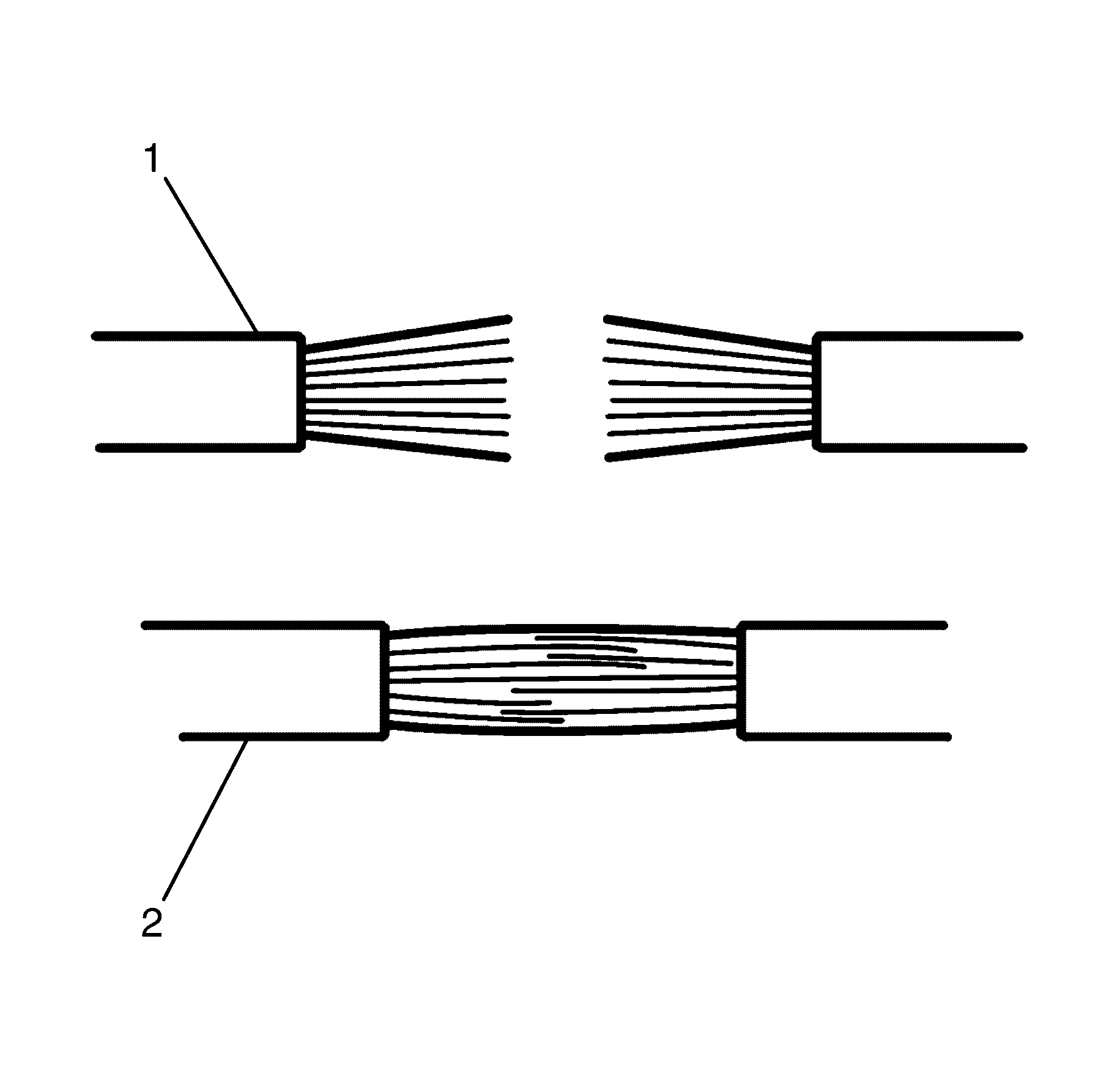
Important: To prevent a short or grounded circuit, remove all the "spikes" from the join before insulating. Spikes can be formed by wire strands or solder itself. These can cut through the insulation.
The Y Junction
The Y junction is used to install a branch connection parallel with the original.
- Use a sharp blade to remove approximately 20 mm (0.8 in) of insulation from the original wire (1).
- Strip the insulation on the branch wire by approximately 20 mm (0.8 in).
- Twist the branch wire around the original wire (2).
- Solder the connection.
- Use PVC tape to insulate the joint.
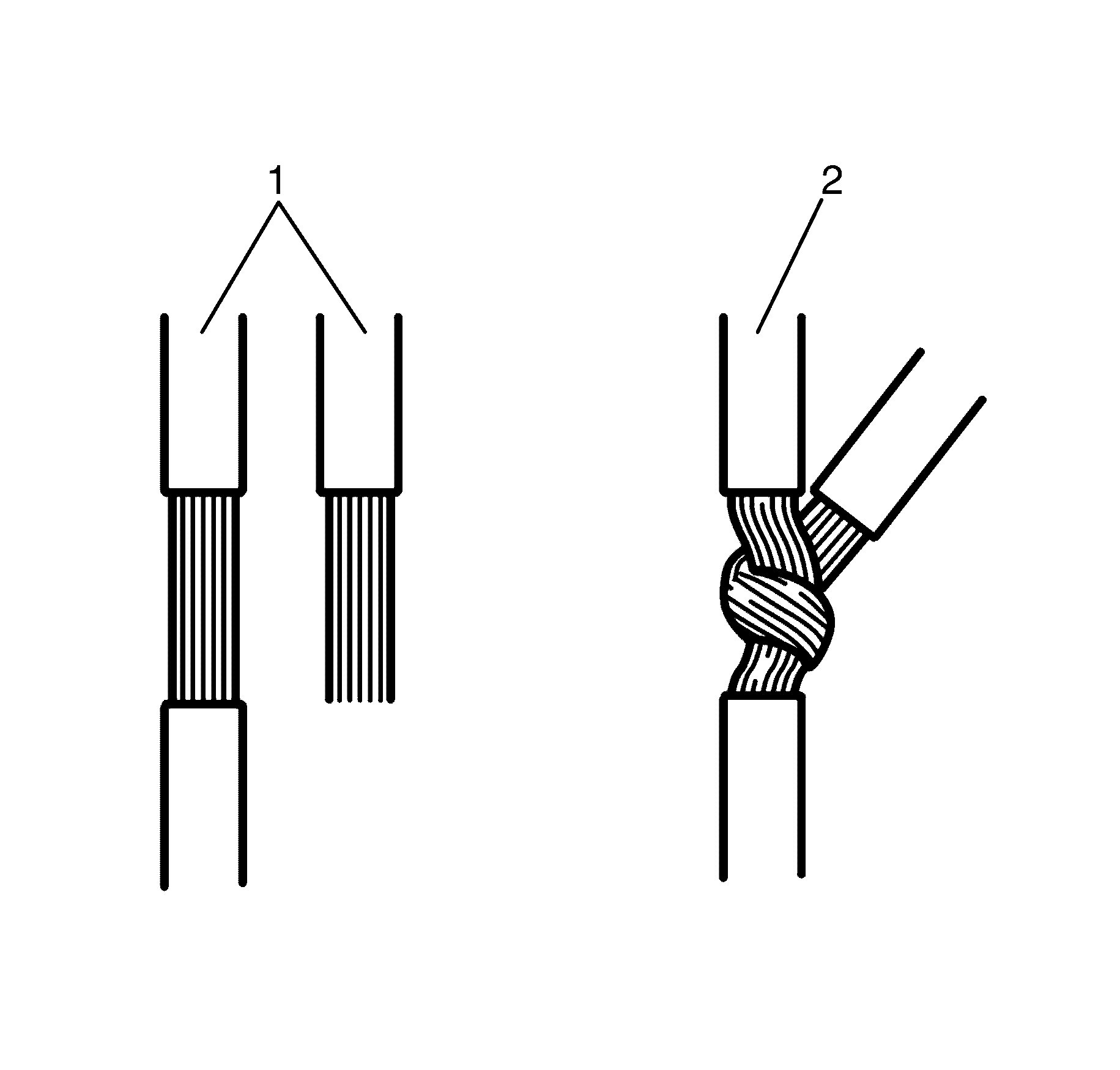
Important: To prevent a short or grounded circuit, remove all the "spikes" from the join before insulating. Spikes can be formed by wire strands or solder itself. These can cut through the insulation.
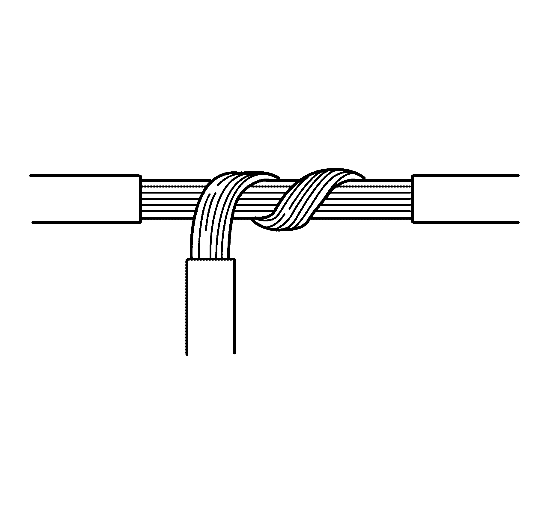
The T Junction
The T junction is used to achieve a 90 degree branch connection.
- Use a sharp blade to remove approximately 20 mm (0.8 in) of insulation from the original wire.
- Strip the insulation on the branch wire by approximately 20 mm (0.8 in).
- Twist the branch wire around the original wire.
- Solder the connection.
- Use PVC tape to insulate the joint.
Important: To prevent a short or grounded circuit, remove all the "spikes" from the join before insulating. Spikes can be formed by wire strands or solder itself. These can cut through the insulation.
