Front Disc Brake Pads Replacement LHD
Removal Procedure
Tools Required
J 23738-A Hand Vacuum Pump.
- Inspect the fluid level in the master cylinder reservoir (1).
- Raise and support the vehicle. Refer to Lifting and Jacking the Vehicle .
- Remove the front wheels. Refer to Tire and Wheel Removal and Installation .
- Install two wheel nuts (1) in reverse to opposite wheel studs to retain the brake disc to the hub.
- Install large G-clamps over the body of the brake caliper (2).
- Tighten the G-clamps evenly until the brake caliper pistons bottom out in each brake caliper bore.
- Remove the G-clamps from the brake caliper (2).
- Remove the brake caliper lower guide pin bolt (1). Discard the bolt (1).
- Pivot the brake caliper (2) upward and secure with heavy mechanics wire (1), or equivalent.
- Remove the brake pads (4) from the brake caliper anchor plate (3).
- Remove the brake pad retainers (5) from the brake caliper anchor plate (3).
- Clean the brake pad brake pad retainer surfaces of the brake caliper anchor plate (3).
- Inspect the brake caliper guide pins and boots for the following conditions:
- If any of the conditions listed are found, overhaul or replace the brake caliper (2).
Caution: Refer to Safety Glasses Caution in the Preface section.
Caution: Refer to Vehicle Lifting Caution in the Preface section.
Caution: Refer to Brake Dust Caution in the Preface section.
Caution: Refer to Brake Fluid Caution in the Preface section.
Caution: Refer to Brake Fluid Irritant Caution in the Preface section.
Notice: Refer to Adding Fluid to the Brake System Notice in the Preface section.
Notice: Refer to Brake Fluid Effects on Paint and Electrical Components Notice in the Preface section.
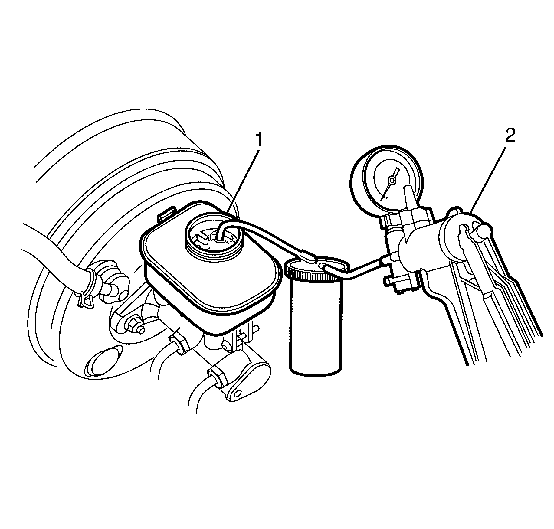
| • | If the brake fluid level is midway between the maximum fill level and the minimum allowable level, no brake fluid needs to be removed from the master cylinder reservoir (1) before proceeding. |
| Important: DO NOT completely empty the master cylinder reservoir (1) or remove any brake lines otherwise complete bleeding of the braking system will be necessary. |
| Important: DO NOT re use the removed fluid. |
| • | If the brake fluid level is higher than midway between the maximum fill level and the minimum allowable level, using a hand vacuum pump (2) syphon the brake fluid to the midway point before proceeding. |
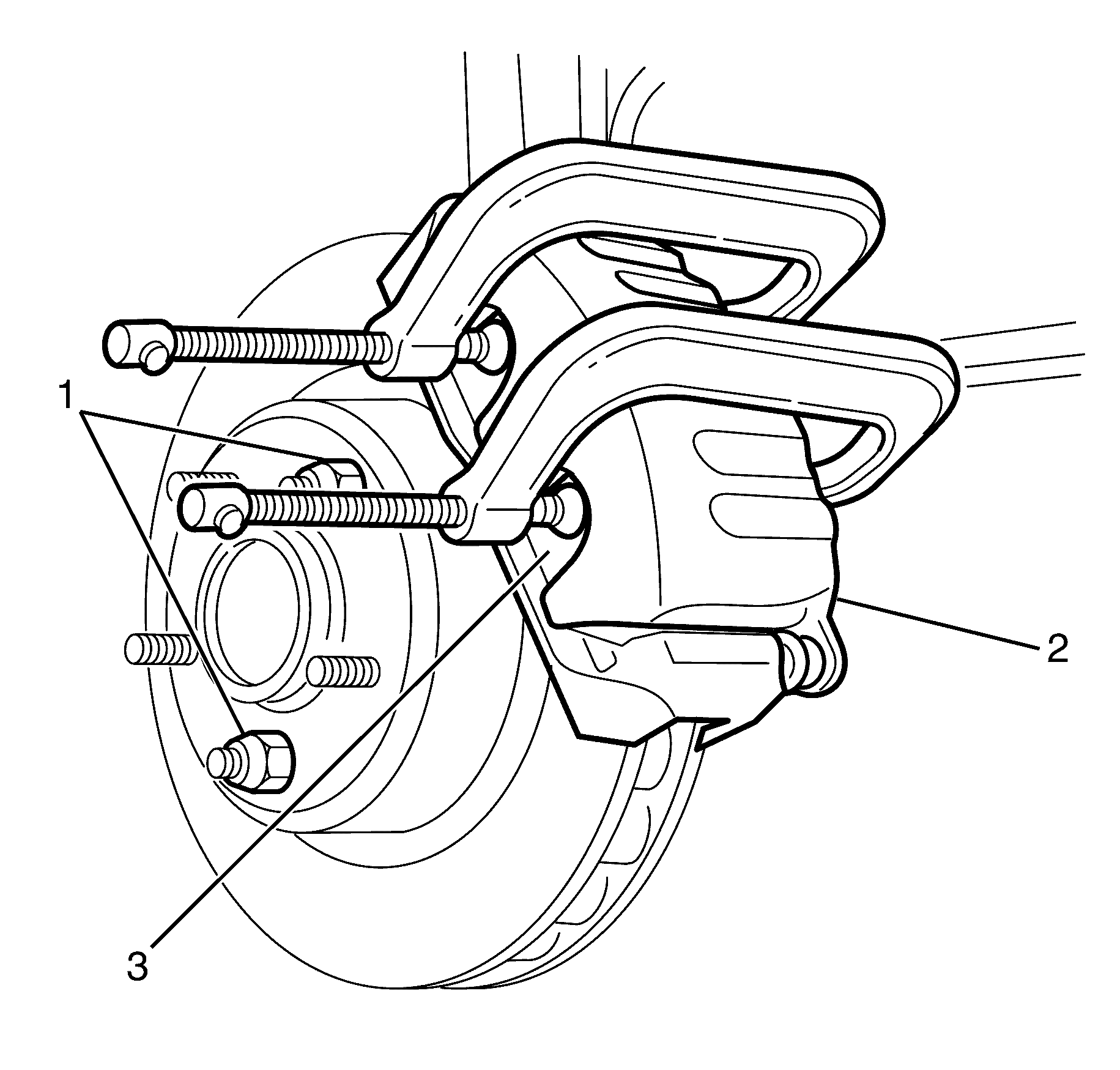
Important: Position the ends of the G-clamps against the rear of the brake caliper (2) and against the outboard brake pad (3).
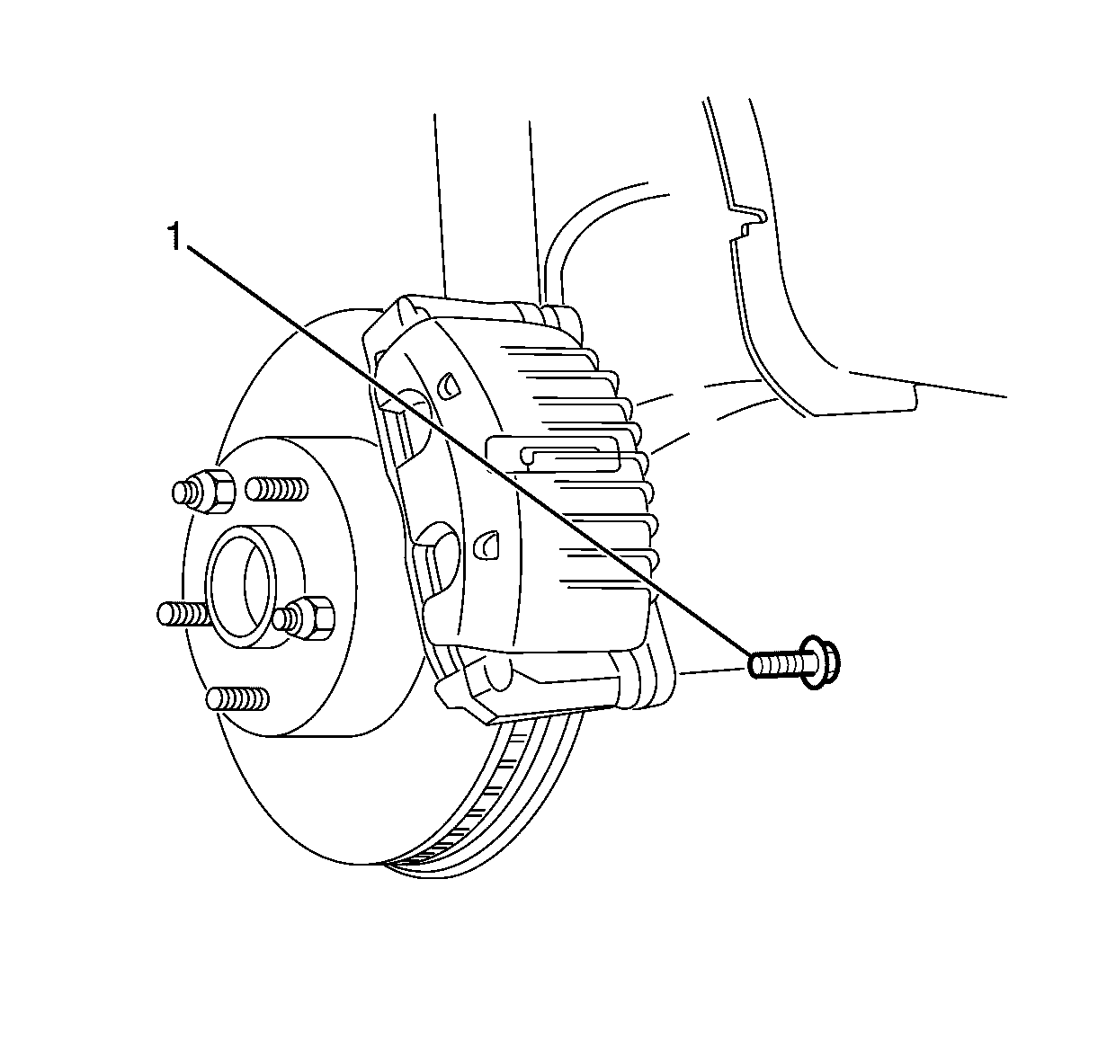
Important: Bolts with micro-encapsulated thread sealant must be discarded after removal.
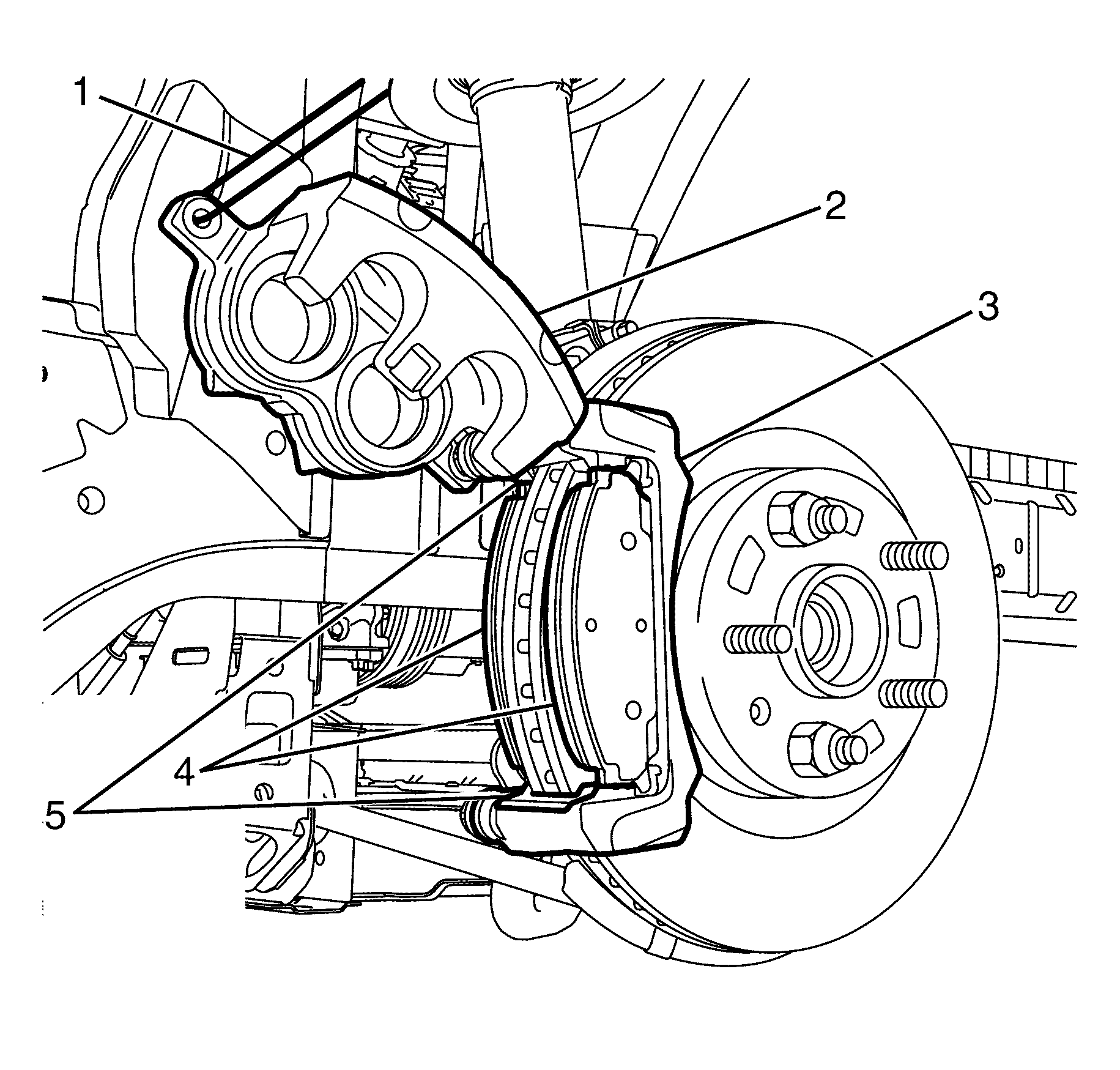
Notice: Support the brake caliper with heavy mechanic wire, or equivalent, whenever it is separated from its mount and the hydraulic flexible brake hose is still connected. Failure to support the caliper in this manner will cause the flexible brake hose to bear the weight of the caliper, which may cause damage to the brake hose and in turn may cause a brake fluid leak.
Important: DO NOT disconnect the brake hose from the brake caliper (2).
Important: Inspect the brake caliper guide pins for freedom of movement and the condition of the guide pin boots. This is achieved by moving the guide pins inboard and outboard within the brake caliper anchor plate (3) bores, without disengaging the slides from the boots.
| • | Restricted brake caliper guide pin movement. |
| • | Too much brake caliper guide pin play in the brake caliper anchor plate (3). |
| • | Seized or binding brake caliper guide pins. |
| • | Split or torn boots. |
Installation Procedure
- Clean the piston to brake pad contact faces as required.
- Install the brake pad retainers (5) to the brake caliper anchor plate (3).
- Install the brake pads (4) to the brake caliper anchor plate (3).
- Remove the mechanics wire (1) or equivalent, and rotate the brake caliper (2) into position over the brake pads (4) and to the brake caliper anchor plate (3).
- Install the NEW lower brake caliper guide pin bolt (1).
- Remove the two wheel nuts retaining the brake disc to the hub.
- Install the front wheels. Refer to Tire and Wheel Removal and Installation .
- Lower the vehicle to the ground.
- With the engine off, gradually apply the brake pedal approximately 2/3 of its travel distance.
- Slowly release the brake pedal.
- Repeat steps 9 and 10 until a firm brake pedal is obtained. This will correctly seat the brake caliper pistons and brake pads.
- Fill the master cylinder reservoir to the correct level. Refer to Master Cylinder Reservoir Filling .
- Burnish (bed in) the brake pads and brake discs. Refer to Brake Pad and Rotor Burnishing .
Caution: Refer to Safety Glasses Caution in the Preface section.
Caution: Refer to Vehicle Lifting Caution in the Preface section.
Caution: Refer to Brake Dust Caution in the Preface section.
Caution: Refer to Brake Fluid Caution in the Preface section.
Caution: Refer to Brake Fluid Irritant Caution in the Preface section.
Notice: Refer to Adding Fluid to the Brake System Notice in the Preface section.
Notice: Refer to Brake Fluid Effects on Paint and Electrical Components Notice in the Preface section.

Important: The brake pads (4) are marked as inner and outer only. Failure to install the brake pads (4) in their correct position will cause the brake pads (4) not to seat correctly in the brake caliper (2).
Notice: Make sure the brake hose is not twisted or kinked after installation. Damage to the hose could result.
Make sure the brake hose is correctly located in its mounting bracket.
Notice: Refer to Fastener Notice in the Preface section.

Tighten
Tighten the bolt to 42 Nm (31 lb ft).
Front Disc Brake Pads Replacement CSV HSV VXR8
Removal Procedure
Tools Required
J 23738-A Hand Vacuum Pump.
- Inspect the fluid level in the master cylinder reservoir (2).
- Raise and support the vehicle. Refer to Lifting and Jacking the Vehicle.
- Remove the front wheels. Refer to Tire and Wheel Removal and Installation.
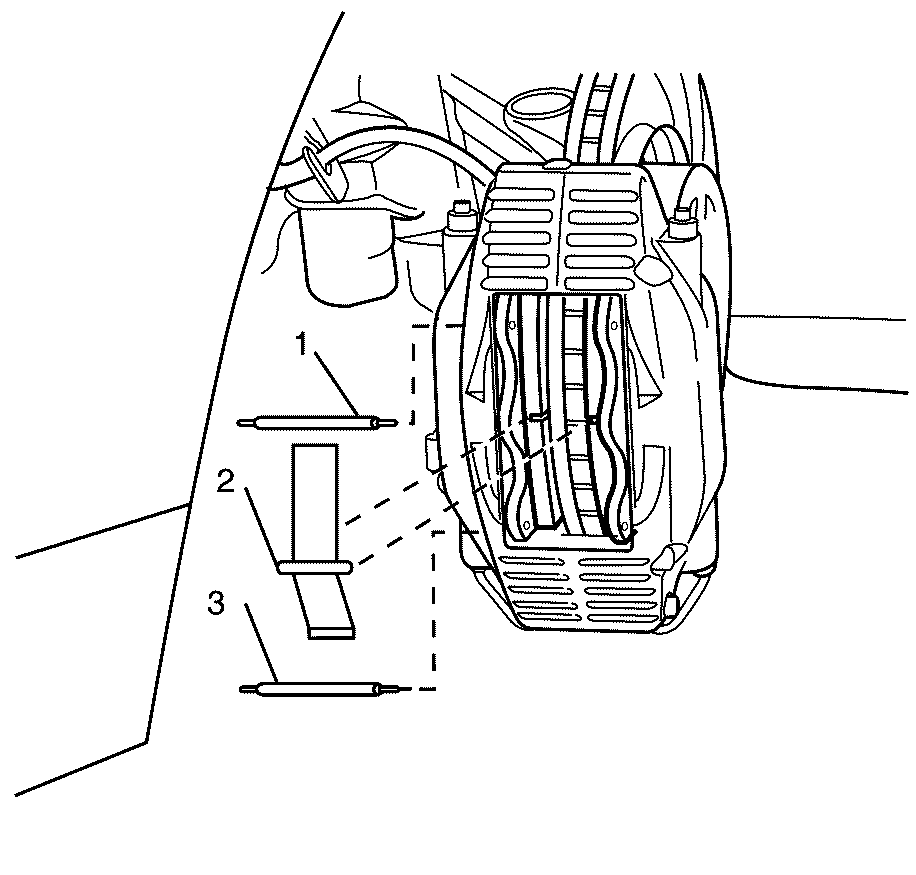
- Use a suitable tool to remove the upper retaining pin (1), lower retaining pin (3) and anti-rattle clip (2) from the brake caliper.
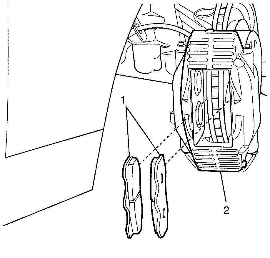
- Remove the brake pads (1) from the brake caliper (2).
- Clean the contact surfaces of the brake caliper pistons with denatured alcohol before pushing the pistons fully back into the brake caliper.
Caution: Refer to Safety Glasses Caution in the Preface section.
Caution: Refer to Vehicle Lifting Caution in the Preface section.
Caution: Refer to Brake Fluid Caution in the Preface section.
Caution: Refer to Brake Dust Caution in the Preface section.
Caution: Refer to Brake Fluid Irritant Caution in the Preface section.
Notice: Refer to Adding Fluid to the Brake System Notice in the Preface section.
Notice: Refer to Brake Fluid Effects on Paint and Electrical Components Notice in the Preface section.
Important: DO NOT completely empty the master cylinder reservoir (2) or remove any brake lines otherwise complete bleeding of the braking system will be necessary.
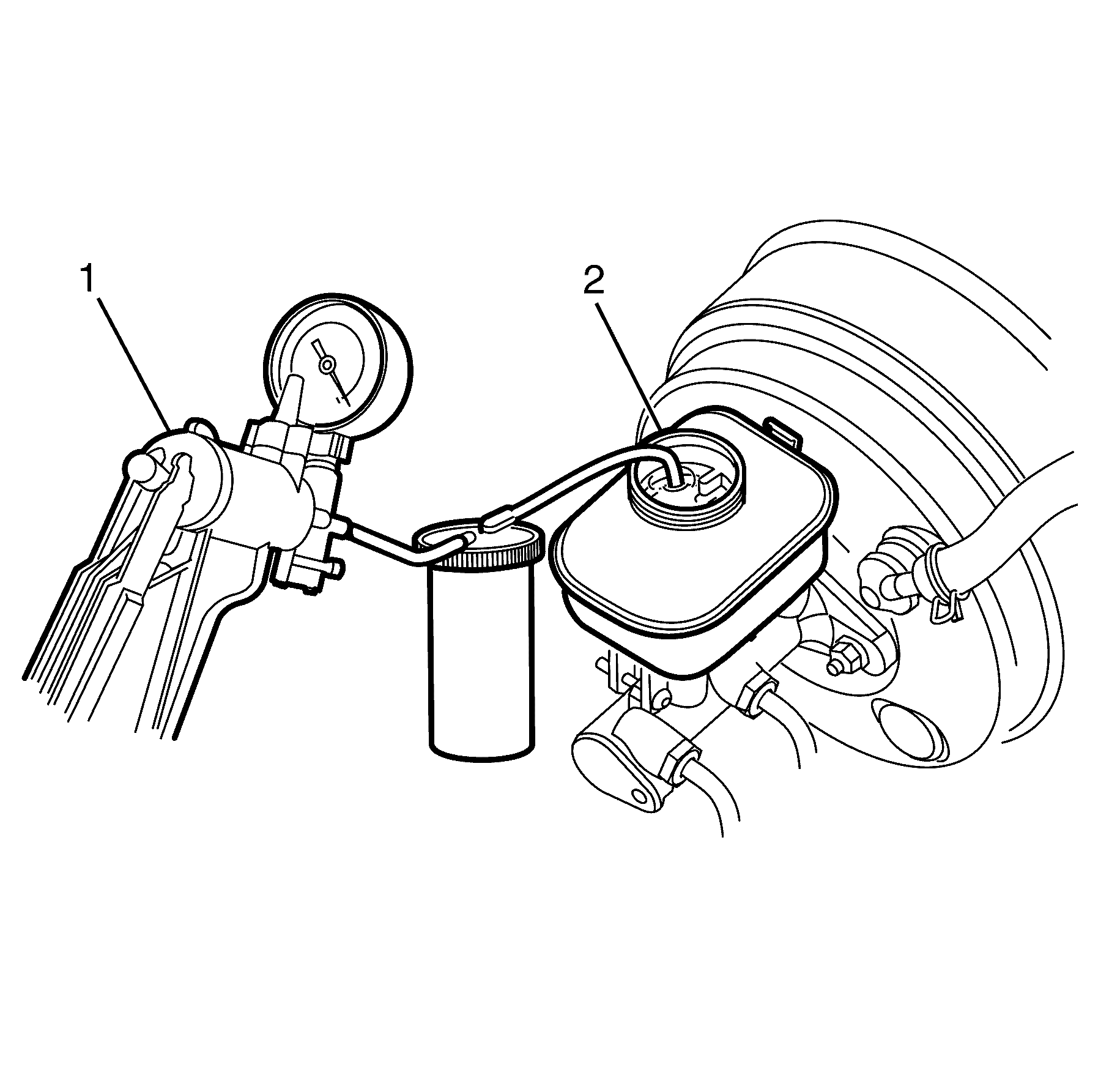
| • | If the brake fluid level is midway between the maximum fill level and the minimum allowable level, no brake fluid needs to be removed from the master cylinder reservoir (2) before proceeding. |
| Important: DO NOT re-use the removed fluid. |
| • | If the brake fluid level is higher than midway between the maximum fill level and the minimum allowable level, syphon the brake fluid to the midway point using a hand vacuum pump (1) before proceeding. |
Important: Brake pads should always be replaced in axle sets.
Installation Procedure
- Clean the piston to brake pad contact faces as required.
- Install the brake pads (1) into the brake caliper (2) against the caliper pistons.
- Install the lower retaining pin (1) into the caliper body through both brake pads (4).
- Install the anti-rattle clip (2) behind the lower retaining pin (1).
- While bending the anti-rattle clip (2) inwards, install the upper retaining pin (3) into the caliper body and through both brake pads (4).
- Install the front wheels. Refer to Tire and Wheel Removal and Installation.
- Lower the vehicle to the ground.
- With the Ignition Off, gradually apply the brake pedal approximately 2/3 of its travel distance.
- Slowly release the brake pedal.
- Repeat steps 10 and 11 until a firm brake pedal application is obtained. This will correctly seat the brake caliper pistons and brake pads.
- Fill the master cylinder reservoir to the correct level. Refer to Master Cylinder Reservoir Filling.
- Burnish (bed in) the brake pads and brake rotors. Refer to Brake Pad and Rotor Burnishing.
Caution: Refer to Safety Glasses Caution in the Preface section.
Caution: Refer to Vehicle Lifting Caution in the Preface section.
Caution: Refer to Brake Fluid Caution in the Preface section.
Caution: Refer to Brake Dust Caution in the Preface section.
Caution: Refer to Brake Fluid Irritant Caution in the Preface section.
Notice: Refer to Brake Fluid Effects on Paint and Electrical Components Notice in the Preface section.
Notice: When adding fluid to the brake master cylinder reservoir, use only Holden specification number HN 1796 (Super DOT 4/DOT 4 Plus) brake fluid from a clean, sealed brake fluid container. The use of any type of fluid other than the recommended type of brake fluid may cause contamination which may result in damage to the internal rubber seals and/or rubber linings of hydraulic brake system components.
Important: Make sure shims are securely affixed to backing plate of the brake pads.

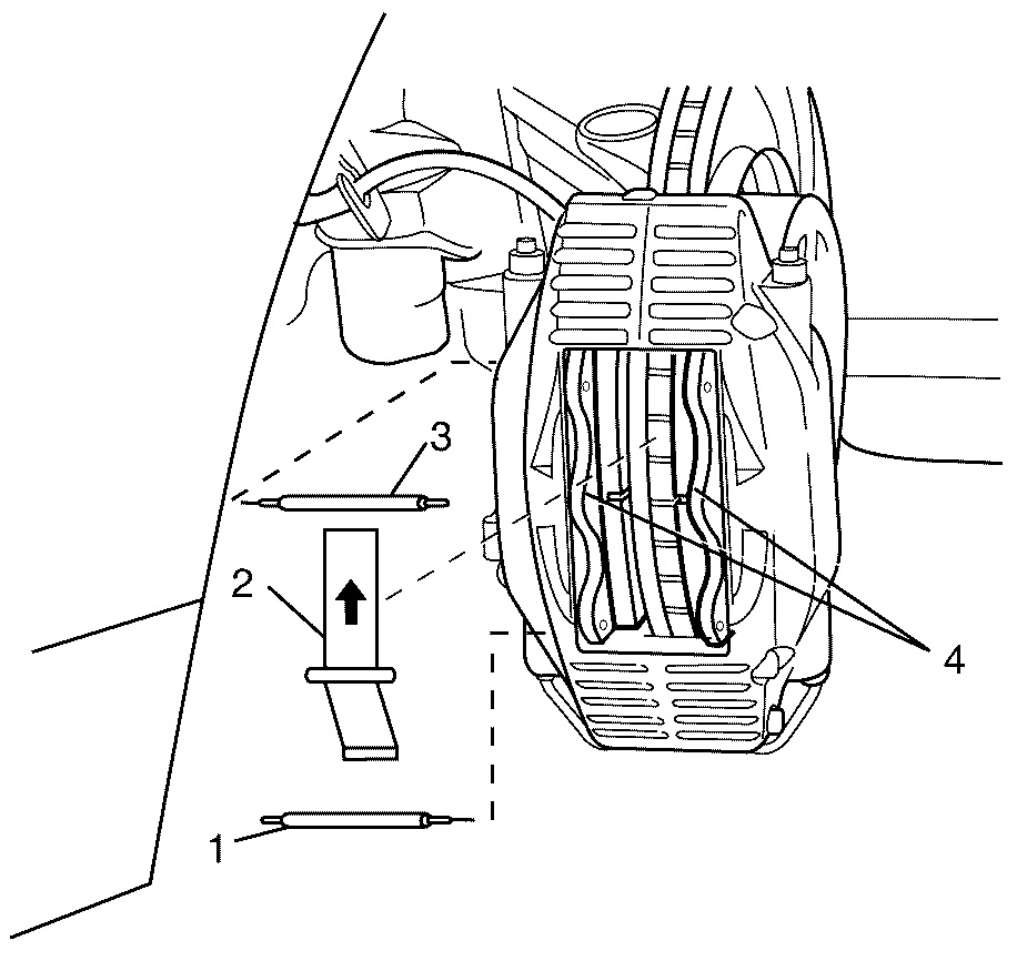
Important:: Arrow located on anti-rattle clip indicates direction of disc rotation. Make sure correct installation of the anti-rattle clip.
Front Disc Brake Pads Replacement RHD
Removal Procedure
Tools Required
J 23738-A Hand Vacuum Pump.
- Inspect the fluid level in the master cylinder reservoir (2).
- Raise and support the vehicle. Refer to Lifting and Jacking the Vehicle .
- Remove the front wheels. Refer to Tire and Wheel Removal and Installation .
- Install two wheel nuts (1) in reverse to opposite wheel studs to retain the brake disc to the hub.
- Install large G-clamps over the body of the brake caliper (2).
- Tighten the G-clamps evenly until the brake caliper pistons bottom out in each brake caliper bore.
- Remove the G-clamps from the brake caliper (2).
- Remove the brake caliper lower guide pin bolt (1).
- Pivot the brake caliper (2) upward and secure with heavy mechanics wire (1), or equivalent.
- Remove the brake pads (4) from the brake caliper anchor plate (3).
- Remove the brake pad retainers (5) from the brake caliper anchor plate (3).
- Clean the brake pad brake pad retainer surfaces of the brake caliper anchor plate (3).
- Inspect the brake caliper guide pins and boots for the following conditions:
- If any of the conditions listed are found, overhaul or replace the brake caliper (2).
Caution: Refer to Safety Glasses Caution in the Preface section.
Caution: Refer to Vehicle Lifting Caution in the Preface section.
Caution: Refer to Brake Dust Caution in the Preface section.
Caution: Refer to Brake Fluid Caution in the Preface section.
Caution: Refer to Brake Fluid Irritant Caution in the Preface section.
Notice: Refer to Adding Fluid to the Brake System Notice in the Preface section.
Notice: Refer to Brake Fluid Effects on Paint and Electrical Components Notice in the Preface section.

| • | If the brake fluid level is midway between the maximum fill level and the minimum allowable level, no brake fluid needs to be removed from the master cylinder reservoir (2) before proceeding. |
| Important: DO NOT completely empty the master cylinder reservoir (2) or remove any brake lines otherwise complete bleeding of the braking system will be necessary. |
| Important: DO NOT re use the removed fluid. |
| • | If the brake fluid level is higher than midway between the maximum fill level and the minimum allowable level, using a hand vacuum pump (1) syphon the brake fluid to the midway point before proceeding. |

Important: Position the ends of the G-clamps against the rear of the brake caliper (2) and against the outboard brake pad (3).

Important: Bolts with micro-encapsulated thread sealant must be discarded after removal.
Important: Make sure the bolt hole is thoroughly cleaned and all micro-encapsulated thread sealant is removed.
Discard the bolt.
Clean the bolt hole.

Notice: Support the brake caliper with heavy mechanic wire, or equivalent, whenever it is separated from its mount and the hydraulic flexible brake hose is still connected. Failure to support the caliper in this manner will cause the flexible brake hose to bear the weight of the caliper, which may cause damage to the brake hose and in turn may cause a brake fluid leak.
Important: DO NOT disconnect the brake hose from the brake caliper (2).
Important: Inspect the brake caliper guide pins for freedom of movement and the condition of the guide pin boots. This is achieved by moving the guide pins inboard and outboard within the brake caliper anchor plate (3) bores, without disengaging the slides from the boots.
| • | Restricted brake caliper guide pin movement. |
| • | Too much brake caliper guide pin play in the brake caliper anchor plate (3). |
| • | Seized or binding brake caliper guide pins. |
| • | Split or torn boots. |
Installation Procedure
- Clean the piston to brake pad contact faces as required.
- Install the new brake pad retainers (5) to the brake caliper anchor plate (3).
- Install the brake pads (4) to the brake caliper anchor plate (3).
- Remove the mechanics wire or equivalent (1), and rotate the brake caliper (2) into position over the brake pads (4) and to the brake caliper anchor plate (3).
- Install the NEW lower brake caliper guide pin to brake caliper anchor plate retaining bolt (1).
- Remove the wheel nuts retaining the brake disc to the hub.
- Install the front wheels. Refer to Tire and Wheel Removal and Installation .
- Lower the vehicle to the ground.
- With the engine off, gradually apply the brake pedal approximately 2/3 of its travel distance.
- Slowly release the brake pedal.
- Repeat steps 9 and 10 until a firm brake pedal is obtained. This will correctly seat the brake caliper pistons and brake pads.
- Fill the master cylinder reservoir to the correct level. Refer to Master Cylinder Reservoir Filling .
- Burnish (bed in) the brake pads and brake discs. Refer to Brake Pad and Rotor Burnishing .
Caution: Refer to Safety Glasses Caution in the Preface section.
Caution: Refer to Vehicle Lifting Caution in the Preface section.
Caution: Refer to Brake Dust Caution in the Preface section.
Caution: Refer to Brake Fluid Caution in the Preface section.
Caution: Refer to Brake Fluid Irritant Caution in the Preface section.
Notice: Refer to Adding Fluid to the Brake System Notice in the Preface section.
Notice: Refer to Brake Fluid Effects on Paint and Electrical Components Notice in the Preface section.

Important: The brake pads (4) are marked as inner and outer only. Failure to install the brake pads (4) in their correct position will cause the brake pads (4) not to seat correctly in the brake caliper (2).
Important: Make sure the brake hose is correctly located in its mounting bracket.
Notice: Make sure the brake hose is not twisted or kinked after installation. Damage to the hose could result.
Notice: Refer to Fastener Notice in the Preface section.

Tighten
Tighten the bolt to 42 Nm (31 lb ft).
