Special Tools
J 41221 Oil Seal Installer
Removal Procedure
- Remove the oil pan. Refer to Oil Pan Replacement .
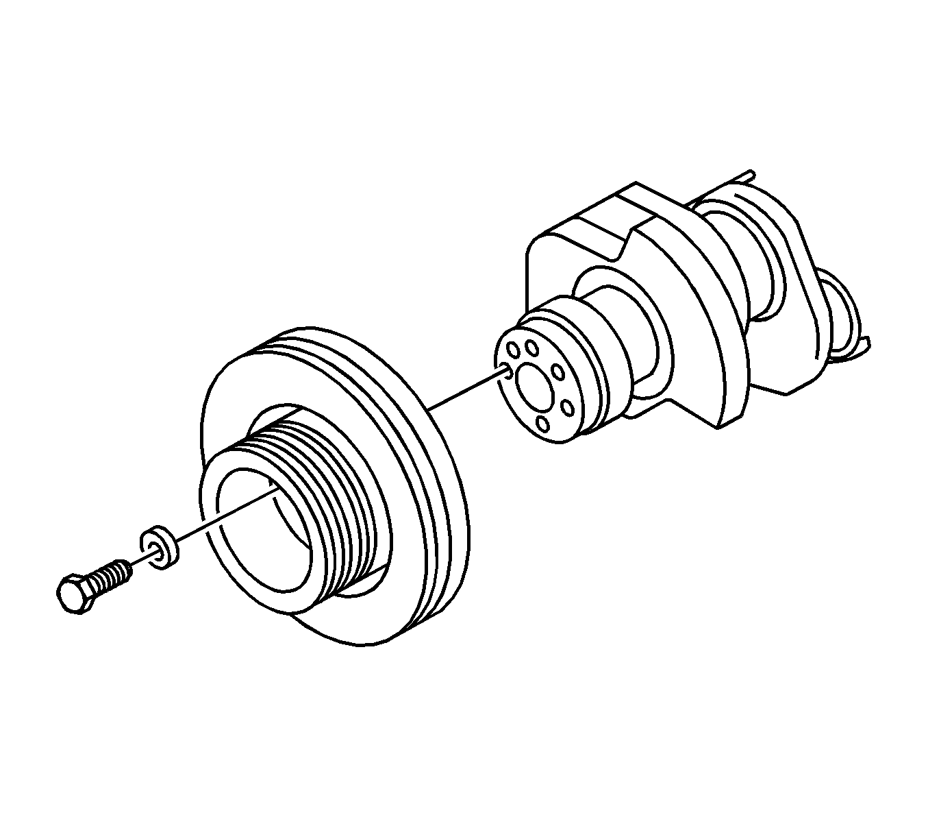
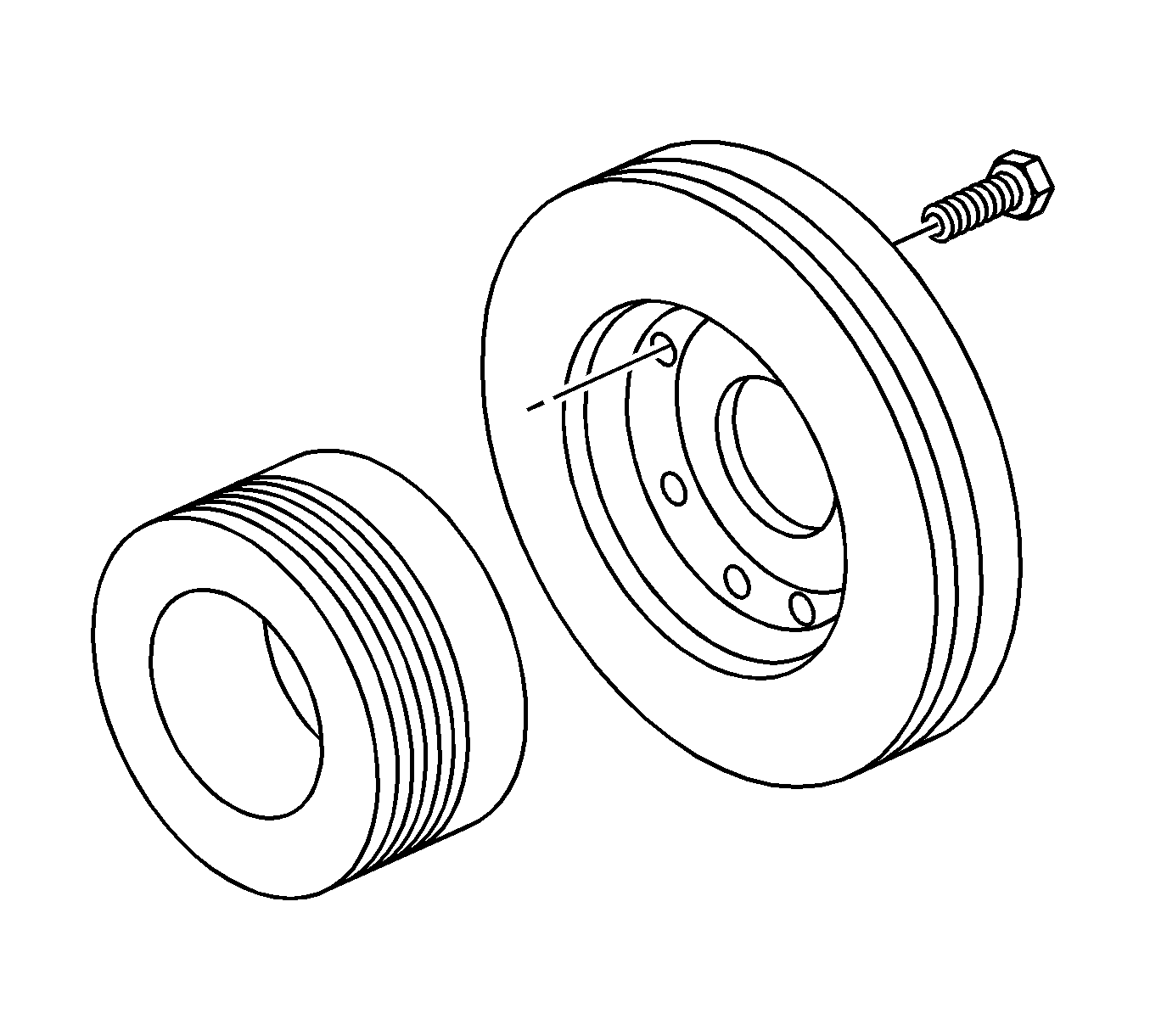
- Remove the crank pulley.
- Remove the damper to the crankshaft pulley.
- Inspect the damper for cracks or breakaway. If cracks or breakaway are present, replace the damper.
- Remove the water duct.
- Remove the O-ring.
- Remove the adjustment plate.
- Remove the gear case cover.
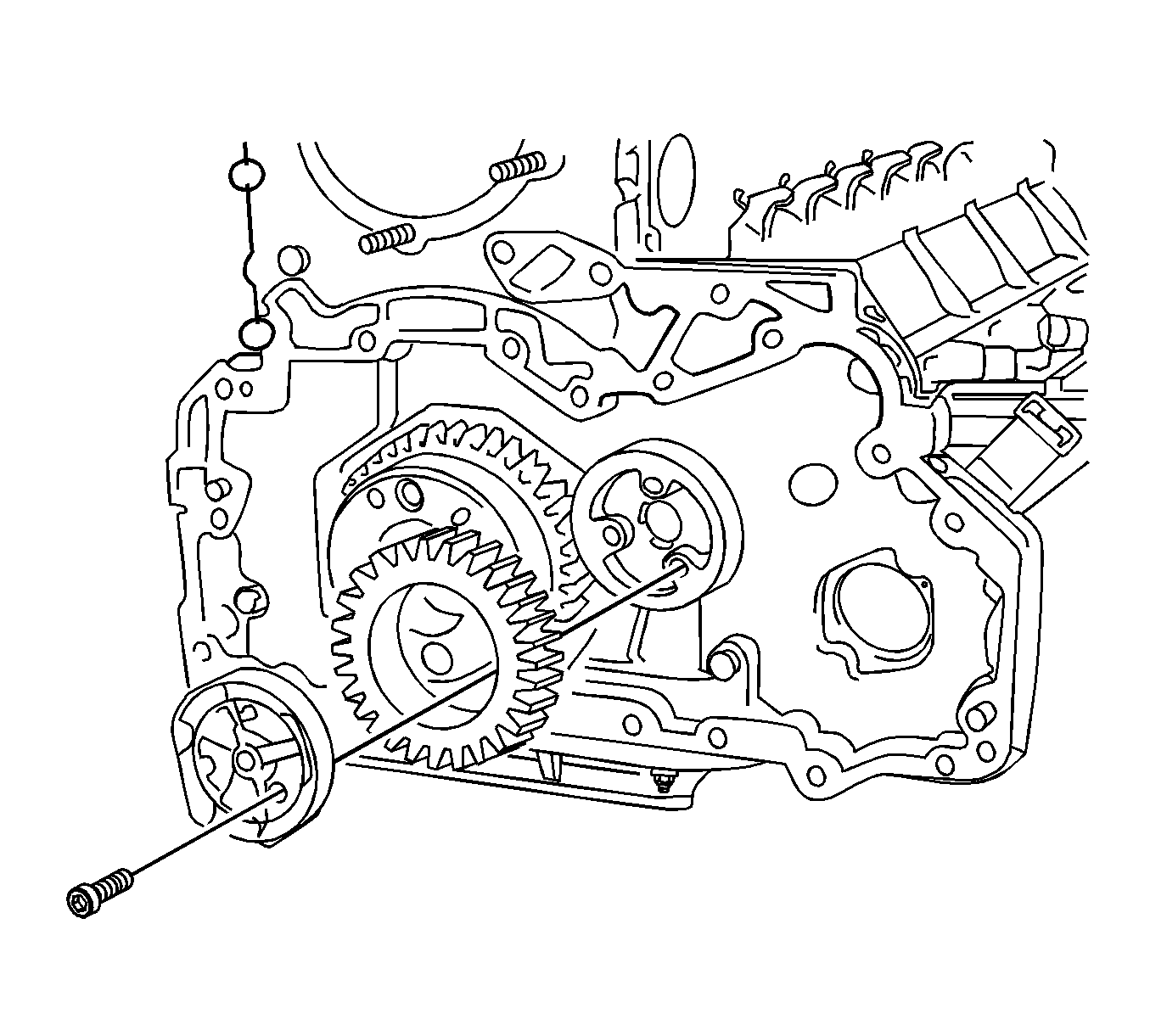
- Remove the idling gear and the idling gear shaft.
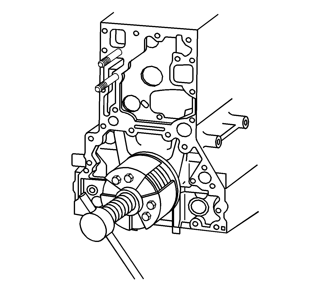
- Install bolts into the gear case replacer holes.
- Remove the gear case.
- Remove the O-ring.
- Remove the front cover oil seal. Refer to Crankshaft Front Oil Seal Replacement .
- Remove the front cover bolts.
- Remove the front cover.
- Using the J 41221 , remove the oil slinger.
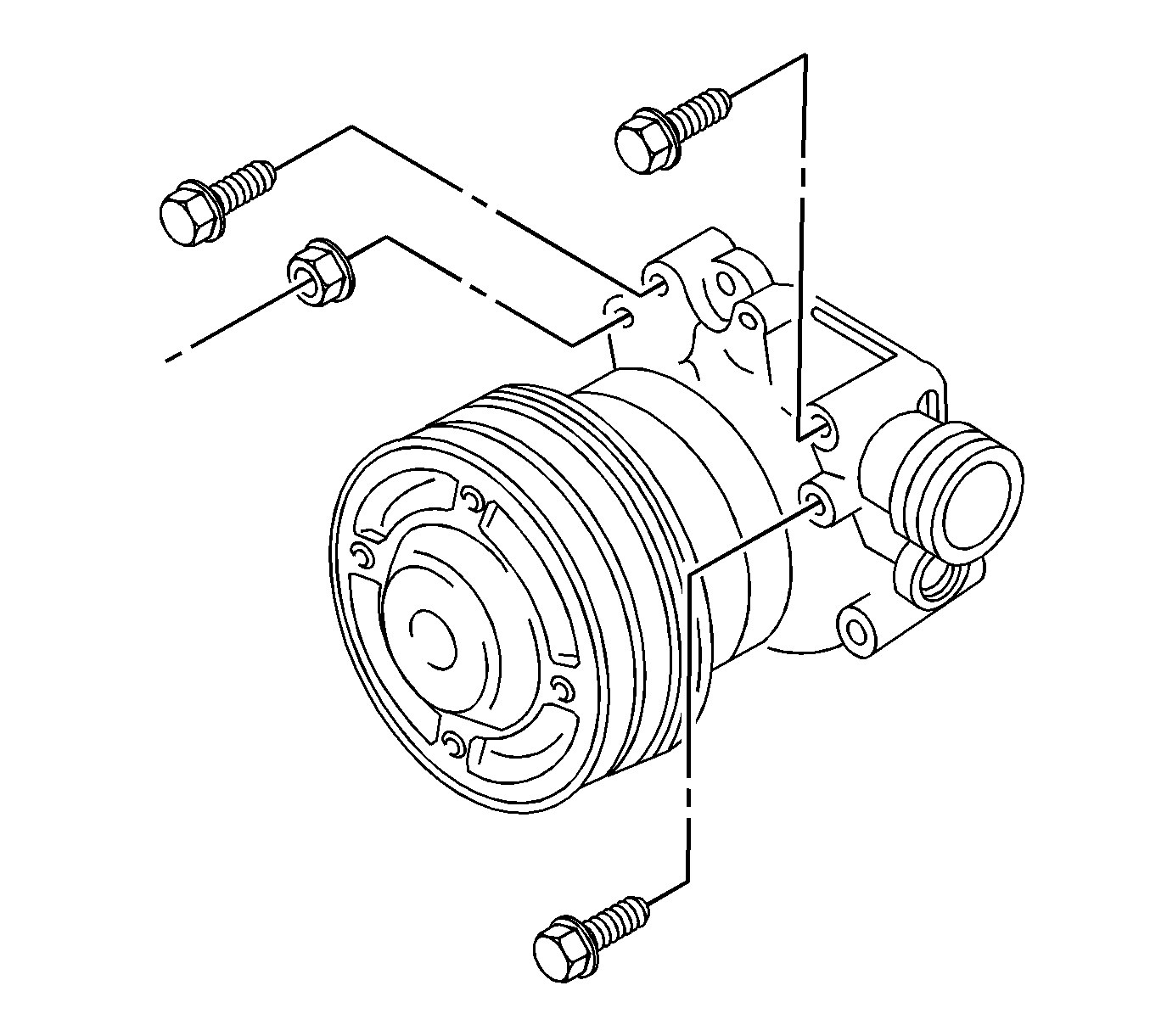
- Remove the water pump bolts.
- Remove the water pump.
- Remove the gear case cover bolts.
- Remove the gear case cover.
- Remove the idling gear shaft.
- Remove the power steering pump idling gear.
- Remove the adjustment plate.
- Remove the gear case.
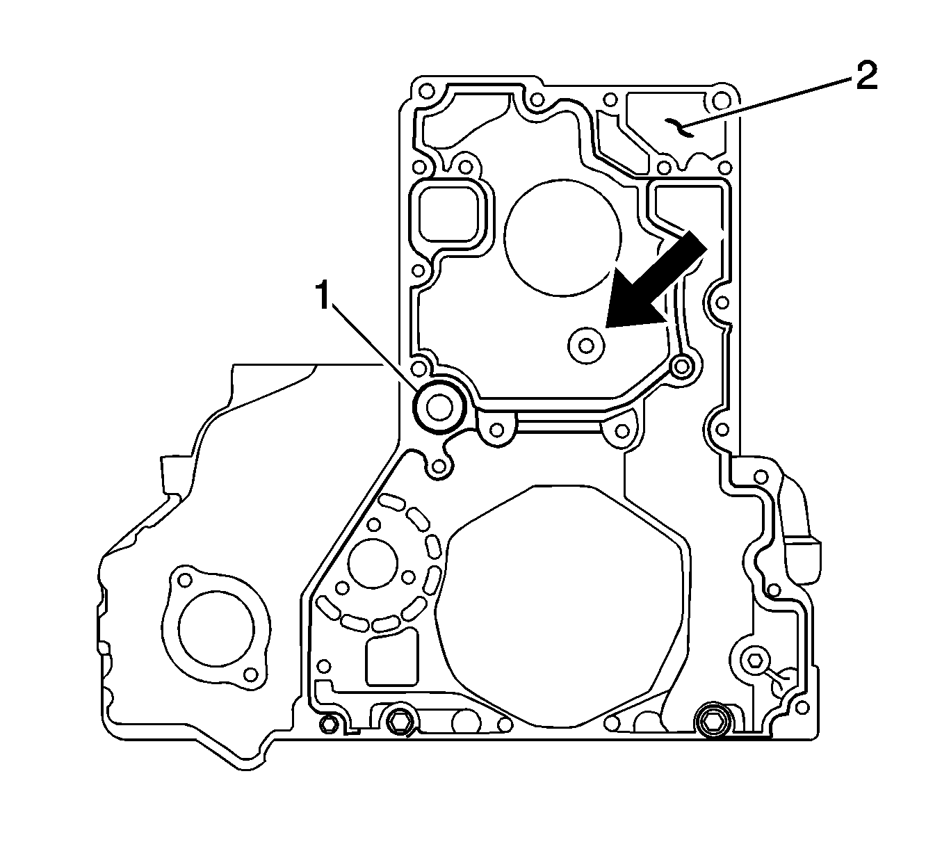
- Remove and discard the O-ring (1).
Important: The oil slinger must be replaced if the front cover oil seal has been removed.
Installation Procedure
- Attach the gear case as follows:
- Secure the adjustment plate.
- Install the power steering pump idling gear.
- Apply oil to the idling gear rotational movement section and attach it to the shaft.
- Point the shaft notch section towards the crankshaft side, and attach it to the gear case.
- Attach the idling gear shaft.
- Position gear case cover.
- Apply a bead of liquid gasket (Three bond No. 1207C), approximately 2-3 mm (0.0787-0.1181 in) to the gear case cover.
- Attach the gear case cover.
- Apply liquid gasket to the water pump.
- Attach the water pump.
- Install the water pump bolts.
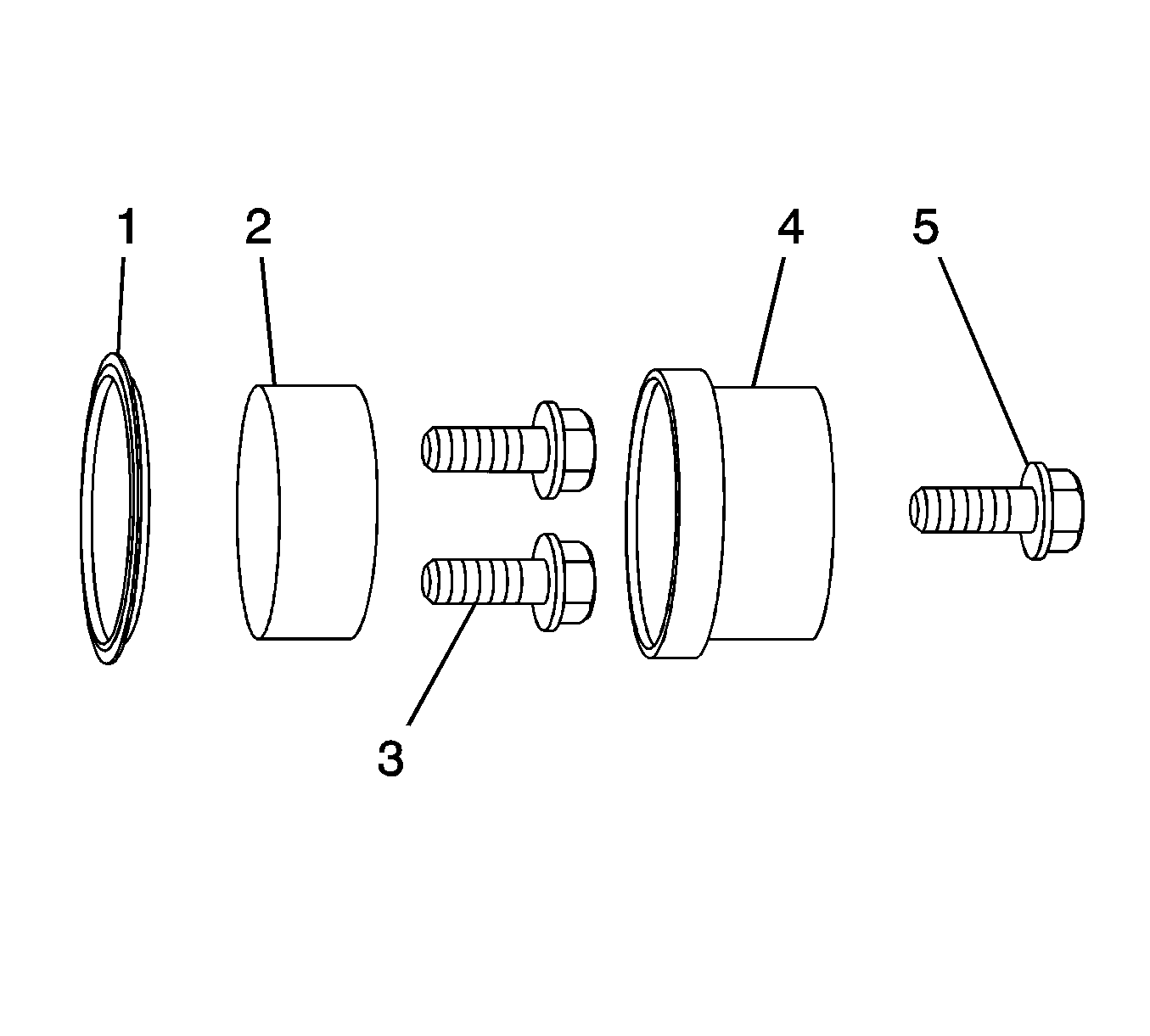
- Apply clean engine oil to the oil slinger.
- Insert the oil slinger into the adapter.
- Install the oil slinger sleeve (4) to the adapter.
- Tighten the center bolt (5) until the sleeve comes in contact with the adapter and stops.
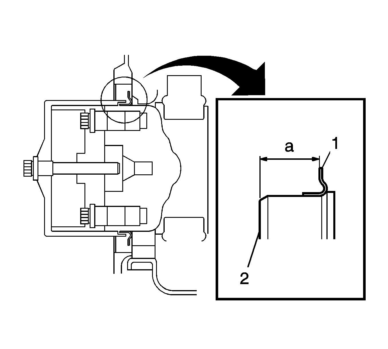
- Inspect the distance (1) between the crankshaft end surface (3) and the oil slinger (2) at several points, ensuring that the measurement is 17.7-18.3 mm (0.6968-0.7205 in).
- Apply sealant on the cylinder block.
- Install the front cover.
- Install the front cover bolts.
- Install the J 41221 on the crankshaft as follows:
- Install the front cover oil seal.
- Measure the crankshaft edge-to-oil seal surface dimensions (1).
- Install the O-ring.
- Position the gear case.
- Remove the bolts from the gear case replacer holes.
- Install the idling gear and the idling gear shaft.
- Install the gear case cover.
- Install the adjustment plate.
- Install the O-ring.
- Install the water duct.
- Install the damper to the crankshaft pulley.
- Install the crank pulley.
- Install the oil pan. Refer to Oil Pan Replacement .
Notice: Refer to Fastener Notice in the Preface section.

Important:
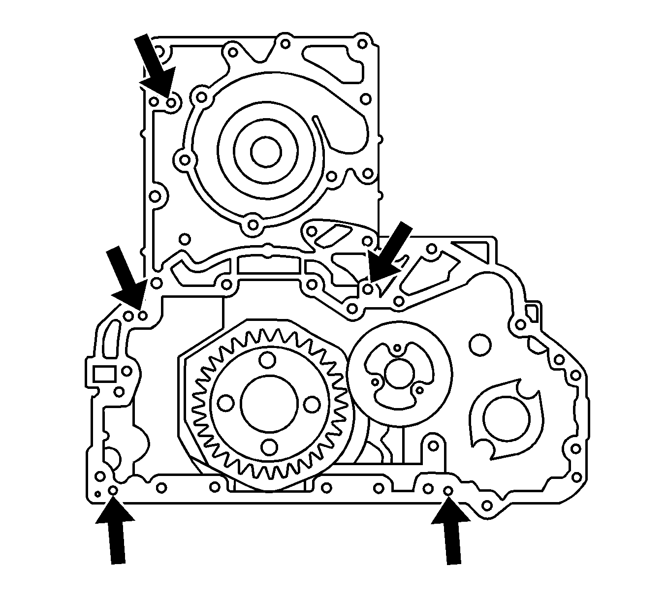
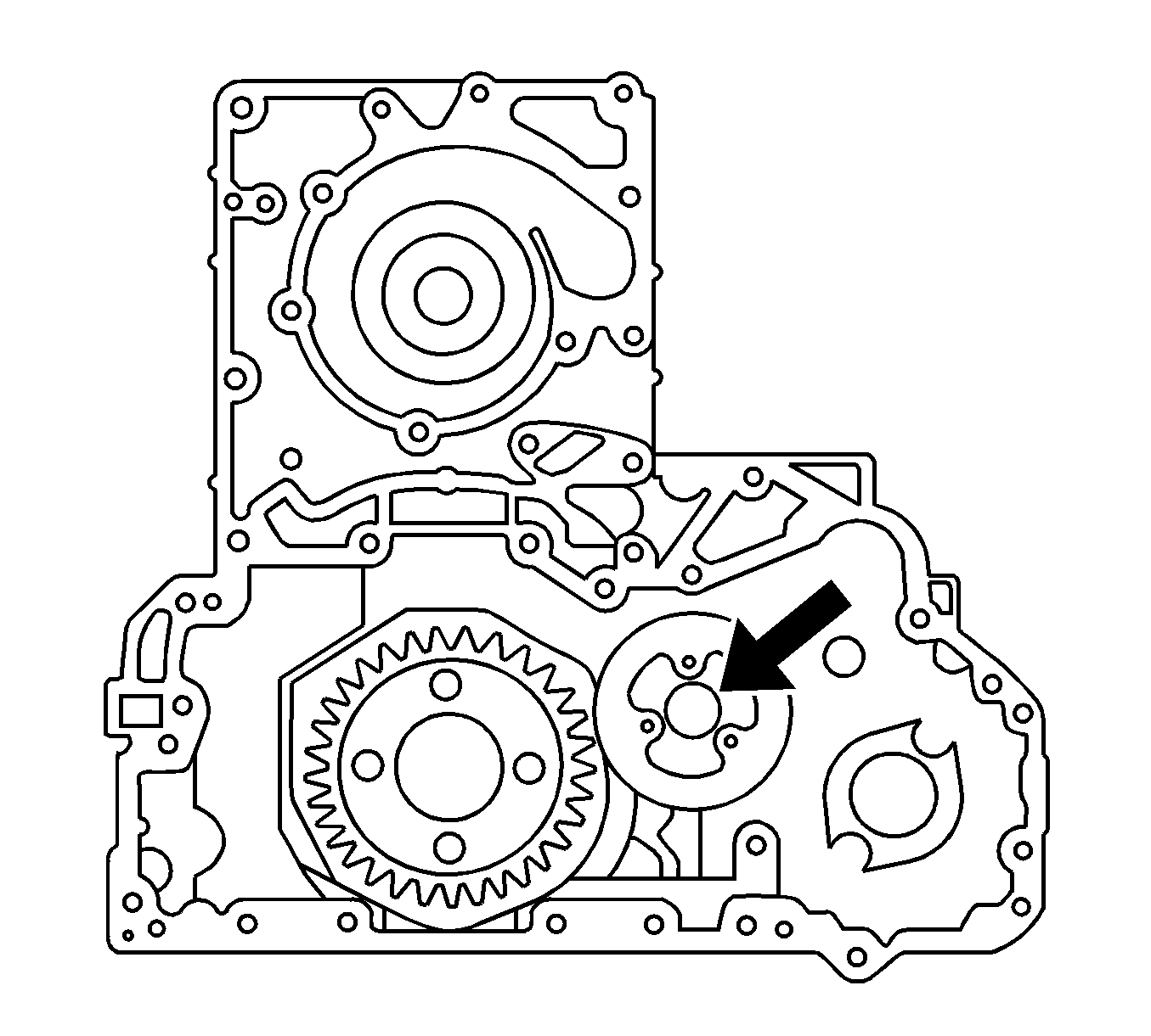
• Do not forget to apply liquid gasket to the arrow sections of the diagram. • Attach the gear case within 7 minutes of applying the liquid gasket to prevent the liquid gasket from drying. • Use Three Bond No. 1208 or CH Dyne 290 to prevent the O-ring from falling out.
| 1.1. | Position the gear case and apply a bead of liquid gasket (Three Bond No. 1207C or No. 1216C), approximately 2-3 mm (0.0787-01181 in) wide. |
| 1.2. | Assemble the O-ring (1). |
| 1.3. | Install the gear case bolts. |
Tighten
Tighten the power steering idling gear bolt to 19 N·m (14 lb ft).

Tighten
Tighten the adjustment plate to 19 N·m (14 lb ft).
Tighten
Tighten the power steering idling gear bolt to 19 N·m (14 lb ft).

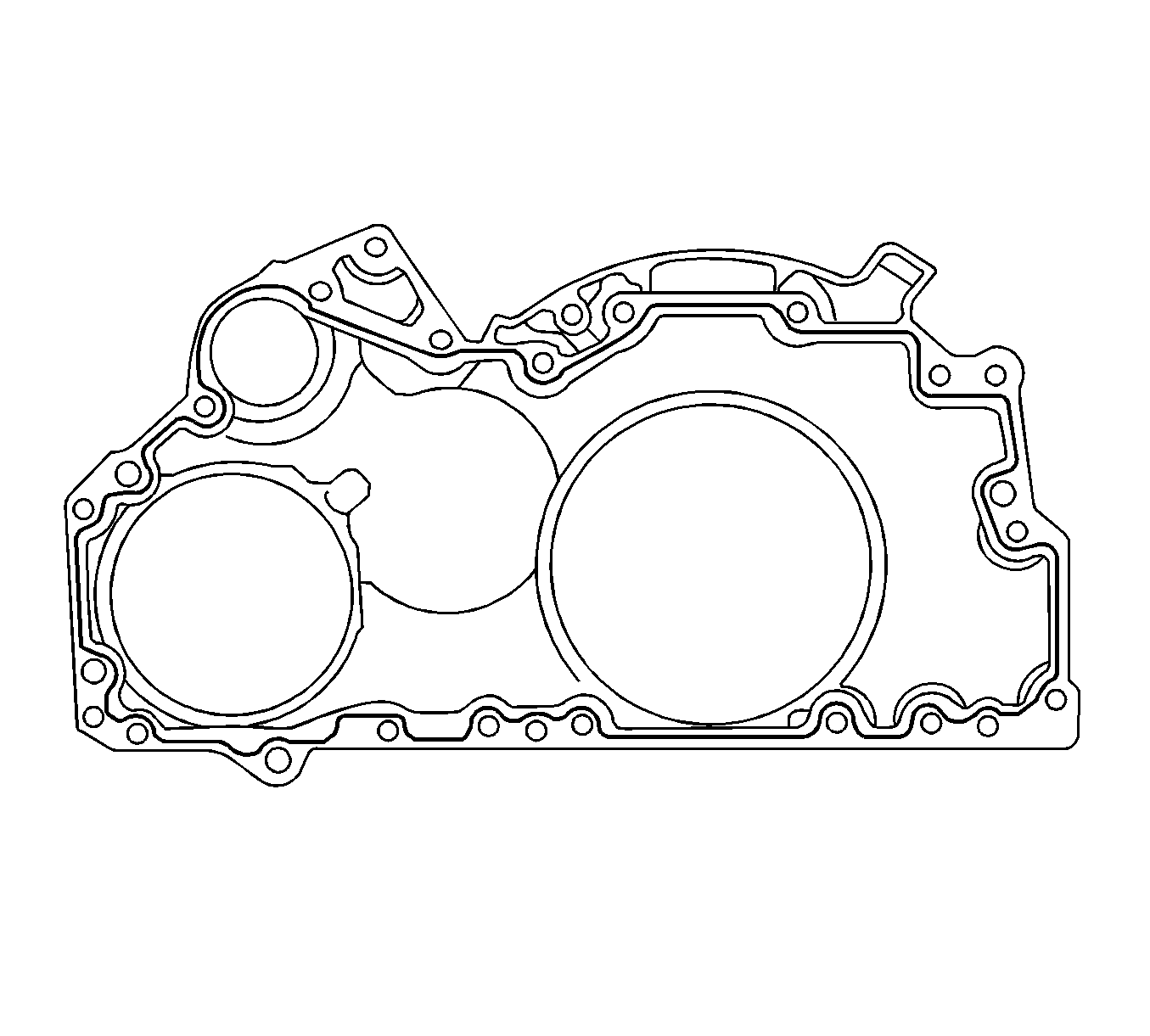
Important: Attach the gear case within 7 minutes of applying the liquid gasket to prevent the liquid gasket from drying.
Tighten
Tighten the gear case bolts to 19 N·m (14 lb ft).
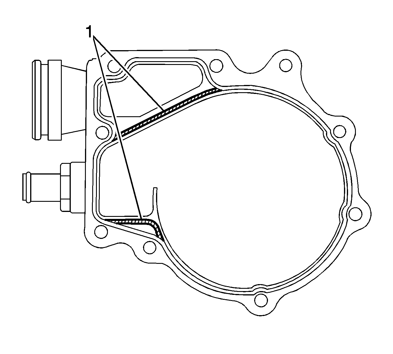
Important:
• Attach water pump within 7 minutes of applying the liquid gasket to prevent the liquid gasket from drying. • Do not apply gasket in area shown (1).

Tighten
Tighten the water pump bolts to 19 N·m (14 lb ft).
Tighten
Tighten the front cover bolts to 19 N·m (14 lb ft).
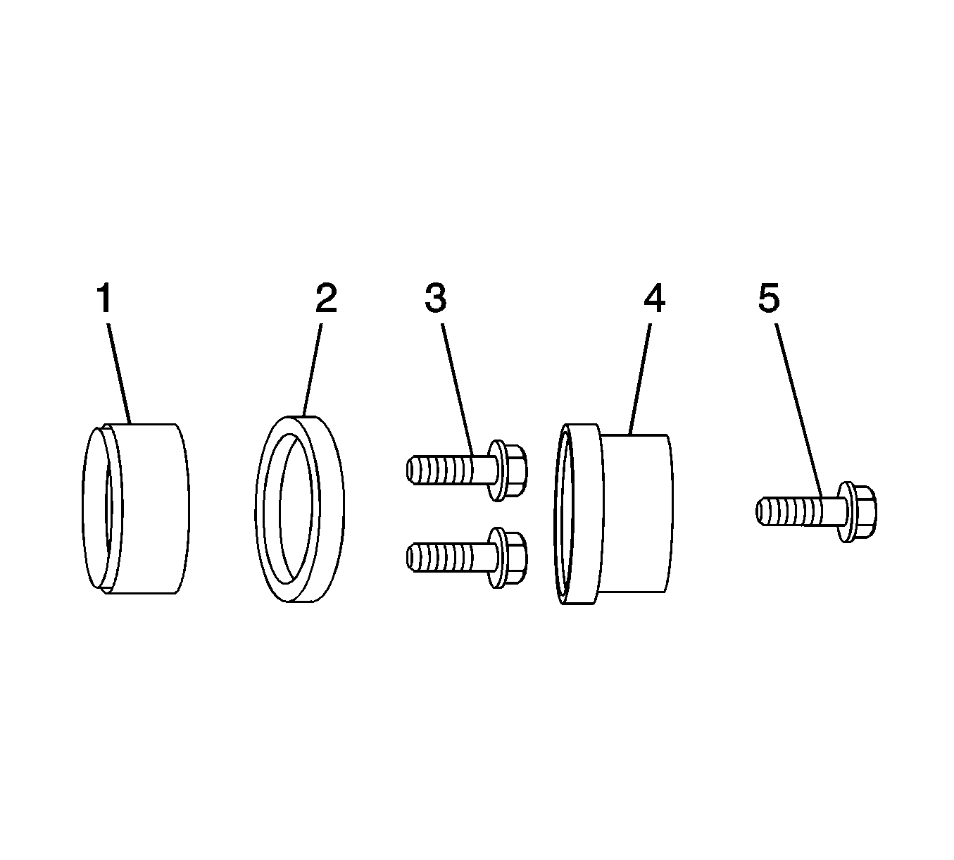
Important: Apply oil to the oil seal lip section.
| 21.1. | Install the oil seal (2) to the crankshaft front cover. |
| 21.2. | Install the front adapter (1) to the oil seal (2). |
| 21.3. | Install the adaptor bolts (3) and sleeve (4). |
| 21.4. | Install the center bolt (5) to the crankshaft. |
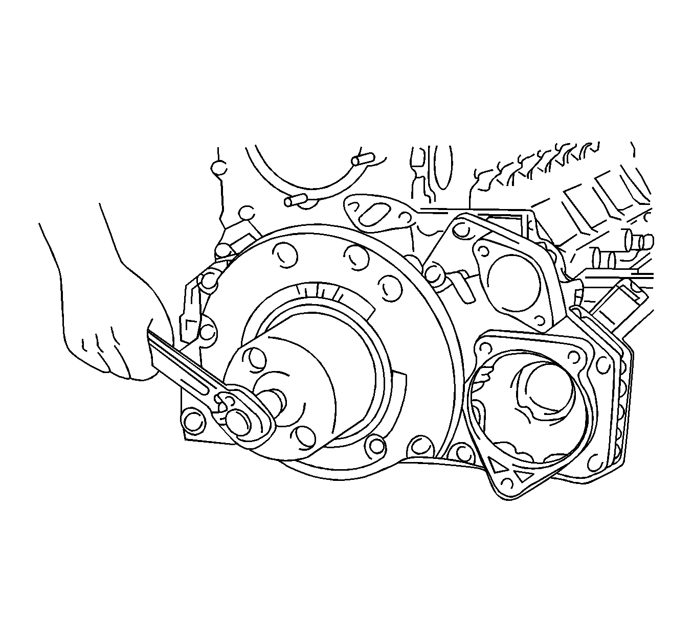
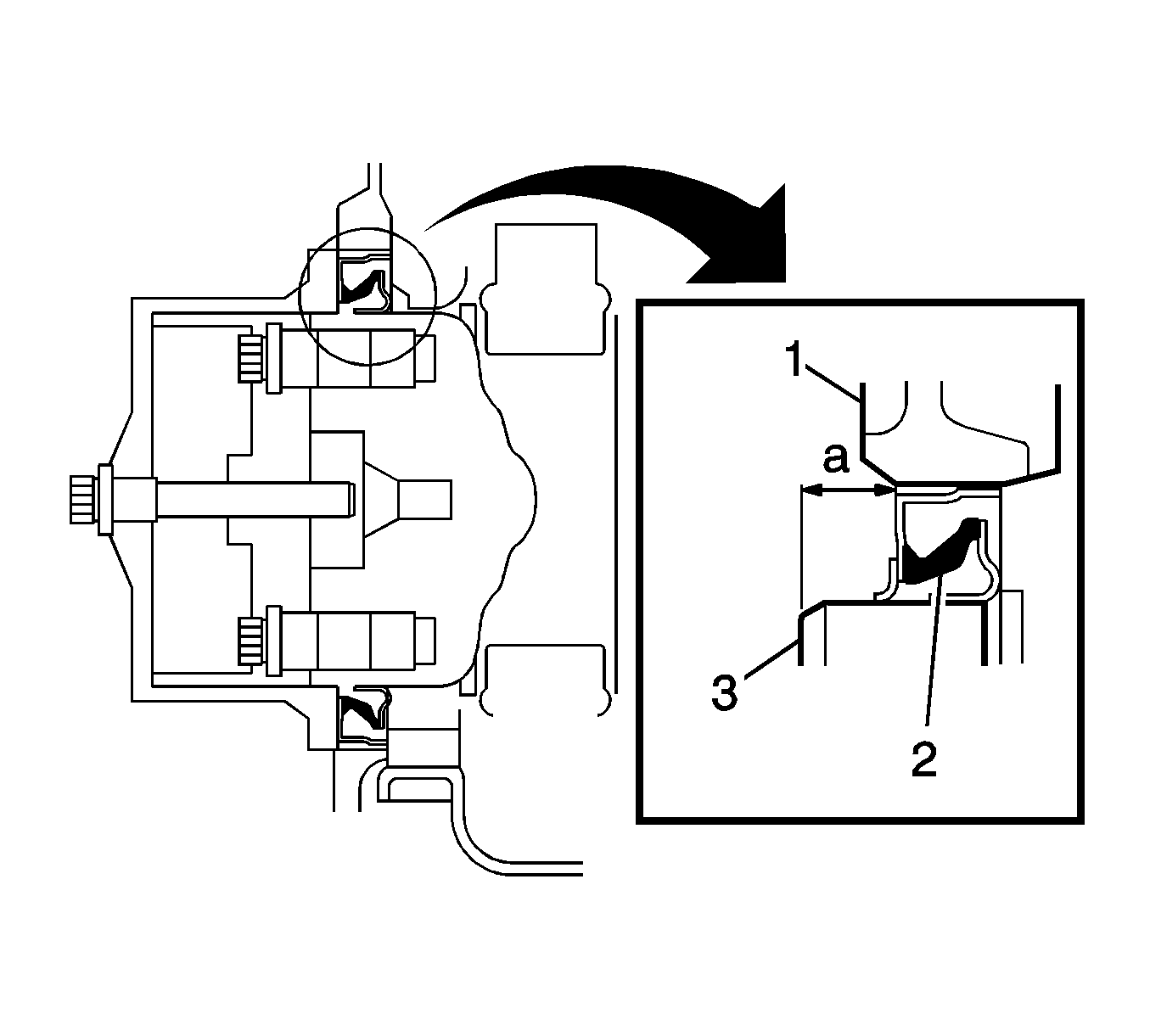
Important: Check that the oil seal is press-fitted with no deflection.
Measure
Oil seal press fit 8.35-8.65 mm (0.3287-0.3406 in).


Tighten
Tighten the damper bolts to 48 N·m (35 lb ft).

Tighten
Tighten the crank pulley bolts to 200 N·m (148 lb ft).
