Parking Brake Shoe Replacement Bendix 229 mm - 9 in
Removal Procedure
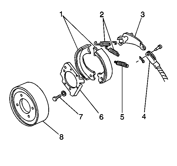
- Remove the drum (6). Refer to Brake Drum Replacement .
- Remove the return springs (2).
- Remove the anchor springs (5).
- Remove the linings (1).
- Spread the brake shoes apart.
- Inspect the linings (1) for contamination.
- Inspect the linings (1) for excessive wear.
- Inspect the springs for distortion.
- Inspect the springs for a loss of tension.
- Inspect the cam lever (3) for grooves at the brake shoe contact points.

The minimum thickness (with bonded linings) is 1.52 mm (0.60 in).
Replace the linings (1) as a set, if necessary.
Replace the springs, if necessary.
Replace the springs, if necessary.
Replace the cam lever (3), if necessary.
Installation Procedure
- Install the linings (1).
- Install the anchor spring (5).
- Install the return springs (2).
- Install the drum (8). Refer to Brake Drum Replacement .
- Adjust the parking brake. Refer to Parking Brake Adjustment.

Place the cam lever (3) in position with the two fingers between the shoe webs.
Lubricate the points where the brake shoes contact the support plate (6).
Parking Brake Shoe Replacement Bendix 254 mm - 10 in
Removal Procedure
- Block the wheels of the vehicle.
- Release the parking brake.
- Remove the propeller shaft. Refer to the appropriate replacement procedure in Propeller Shaft:
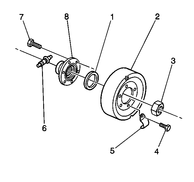
- Remove the flange nut (3).
- Remove the drum (2) and flange (8).
- Disconnect the O-ring seal (1) in the flange bore.
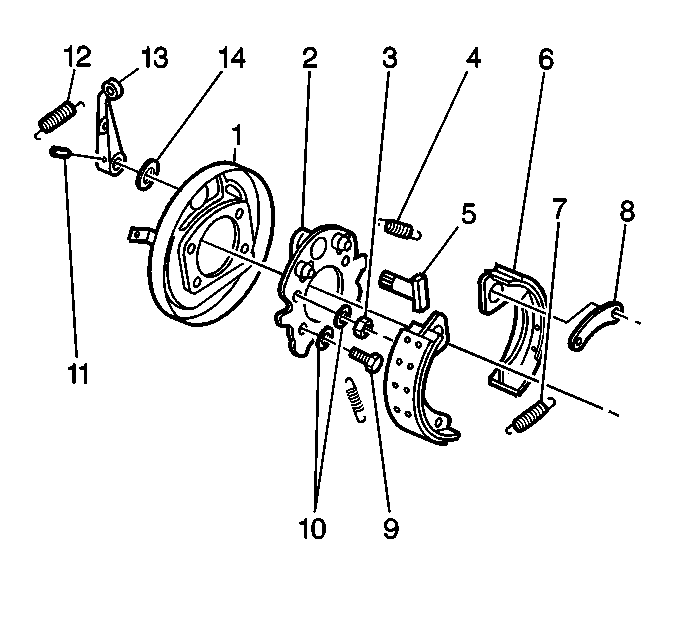
- Remove the springs (4,7).
- Remove the adjuster (6).
- Remove the shoes (6).
- Inspect the return spring. Ensure that the free length is 68 mm (2.68 in).
- Inspect the shoes (6).


| • | Replace the shoes if the web at the point of the cam contact is severely worn. |
| • | Replace the shoes if the riveted lining is 0.2 mm (0.008 in) from the rivet heads or on bonded shoes when worn to 2.0 mm (0.08 in). |
Installation Procedure
- Install the shoes (6).
- Install the adjuster (6).
- Install the springs (4,7).
- Install the drum (2) and the flange (8).
- Install the flange nut (3).
- Stake the nut in two places, 180 degrees apart.
- Install the propeller shaft.
- Adjust the brake shoes.
- Verify that the brakes are functioning correctly.


Notice: Use the correct fastener in the correct location. Replacement fasteners must be the correct part number for that application. Fasteners requiring replacement or fasteners requiring the use of thread locking compound or sealant are identified in the service procedure. Do not use paints, lubricants, or corrosion inhibitors on fasteners or fastener joint surfaces unless specified. These coatings affect fastener torque and joint clamping force and may damage the fastener. Use the correct tightening sequence and specifications when installing fasteners in order to avoid damage to parts and systems.
Tighten
Tighten the flange nut to 784 N·m (579 lb ft).
