For 1990-2009 cars only
Removal Procedure
Tools Required
J 23523-F Crankshaft Balancer Remover and Installer
- Remove the engine front cover. Refer to Engine Front Cover Replacement .
- Remove the crankshaft position sensor reluctor ring.
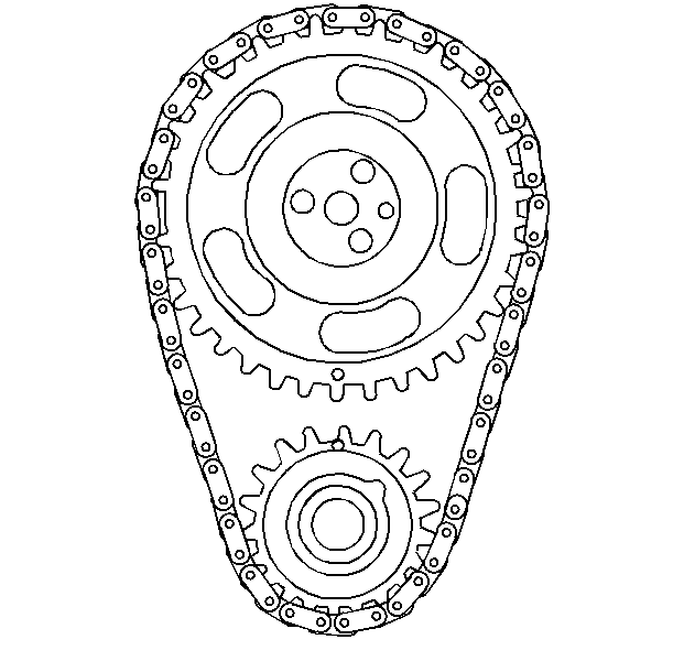
- Align the camshaft sprocket and the crankshaft sprocket alignment marks.
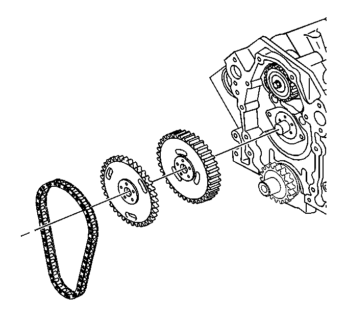
- Remove the timing chain and sprockets.
Installation Procedure
Tools Required
| • | J 23523-F Crankshaft Balancer Remover and Installer |
| • | J 5825-A Installer |
- Rotate the camshaft sprocket so that the timing mark on the balance shaft drive gear is straight up.
- Remove the drive gear. Turn the balance shaft so that the timing mark on the driven gear points down.
- Reinstall the camshaft drive gear onto the camshaft.
- Install the timing chain and the camshaft sprocket.
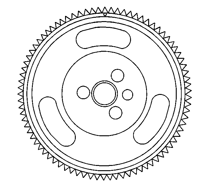
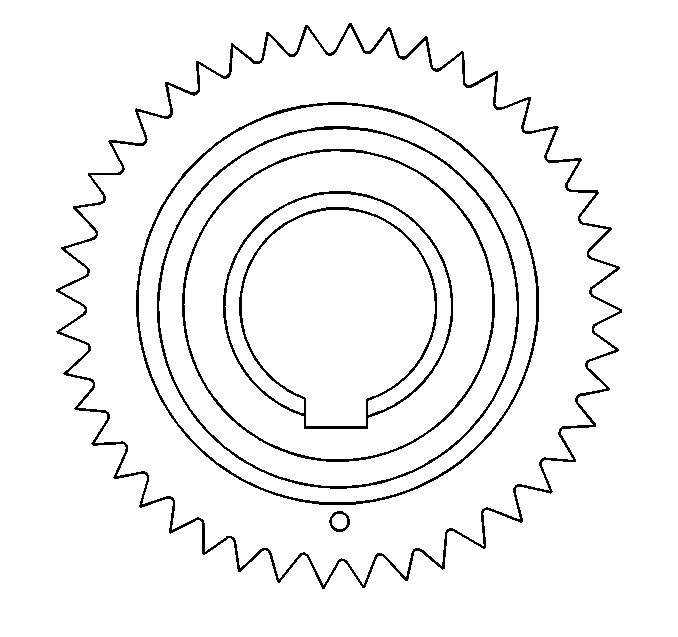
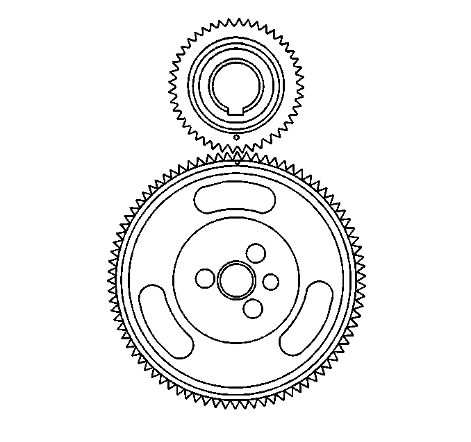
| • | Ensure that the timing marks align. |
| • | The number four cylinder should be at the top dead center of its compression stroke. When installing the distributor, position the rotor so that it faces the number four terminal. |
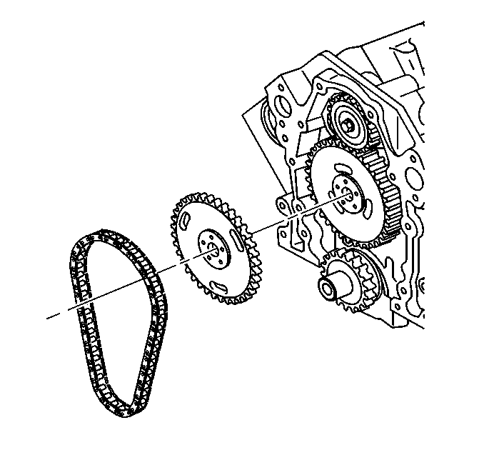
Tighten
Tighten the camshaft sprocket bolts to 25 N·m (18 lb ft).
Notice: Use the correct fastener in the correct location. Replacement fasteners must be the correct part number for that application. Fasteners requiring replacement or fasteners requiring the use of thread locking compound or sealant are identified in the service procedure. Do not use paints, lubricants, or corrosion inhibitors on fasteners or fastener joint surfaces unless specified. These coatings affect fastener torque and joint clamping force and may damage the fastener. Use the correct tightening sequence and specifications when installing fasteners in order to avoid damage to parts and systems.
