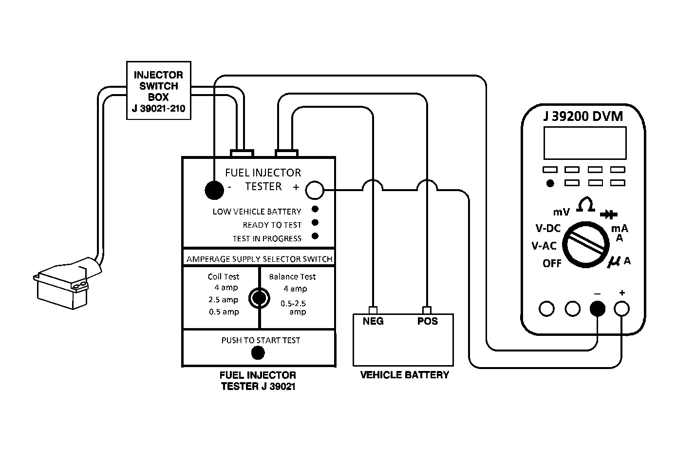
Test Description
The numbers below refer to the step numbers on the diagnostic able.
-
This step is the setup step for performing the injector coil test. Also read the instructions included with the tools used for this test.
-
The engine coolant temperature affects the ability of the tool to detect a malfunctioning or a damaged injector. If the engine coolant temperature is not between 50°F and 95°F, allow the vehicle to warm or cool as necessary.
-
Due to a current surge, the first second of the voltage reading may be inaccurate; therefore, begin recording after the first second of the voltage reading. The voltage specification should be within range. The voltage reading may increase throughout the test as the injector windings warm up and the resistance changes. An erratic voltage reading (one that jumps up and down) would indicate an intermittent connection within the fuel injector.
Step | Action | Value(s) | Yes | No |
|---|---|---|---|---|
1 | Was the Powertrain On-Board Diagnostic (OBD) System Check performed? | -- | ||
Is the engine coolant temperature within the specified value? | 10°-35°C | |||
Allow the engine to warm or cool as necessary. Is the engine coolant temperature within the specified value? | 10°-35°C | -- | ||
|
Important: Perform the following test for each injector.
Important: Voltage may climb during the test. Watch for erratic readings (voltage that jumps up and down). Do any of the injector voltage readings fall outside of the specified value? | 5.44-7.53V | |||
5 | Replace the fuel injector and poppet nozzle assembly that was not within the specified value. Refer to Fuel Injector Replacement (Central SFI) . Is the action complete? | 5.44-7.53V | -- | |
6 |
Does the engine start and continue to run? | -- | ||
7 |
Are there any DTCs displayed? | -- | Go to The Applicable DTC Table | |
8 | Use the scan tool in order to display the Capture Info and the Review Info. Are there any DTCs displayed that have not been diagnosed? | -- | Go to The Applicable DTC Table | System OK |
