For 1990-2009 cars only
Removal Procedure
- Remove the radiator.
- Remove the a/c condenser, if equipped.
- Remove the engine front cover and the crankshaft position reluctor ring.
- Loosen the balance shaft driven gear bolt using the following steps:
- Remove the timing chain and sprockets.
- Remove the balance shaft drive and driven gears.
- Remove the valve lifter retainer.
- Remove the bolt and the balance shaft retainer.
- Tap on the balance shaft using a soft-faced hammer in order to remove the balance shaft.
- Clean all sealing surfaces.
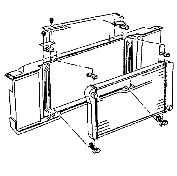
Refer to Radiator Replacement in Engine Cooling.
Refer to Condenser Replacement in HVAC.
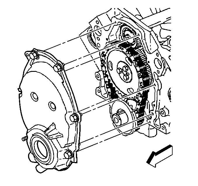
Refer to Engine Front Cover Replacement .
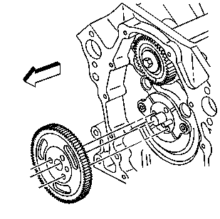
| 4.1. | In order to hold the camshaft sprocket, use a wrench on one of the bolts. |
| 4.2. | Loosen, then remove the balance shaft bolt and the washer. |
| 4.3. | Remove the wrench from the camshaft sprocket. |
Refer to Timing Chain and Sprocket Replacement .
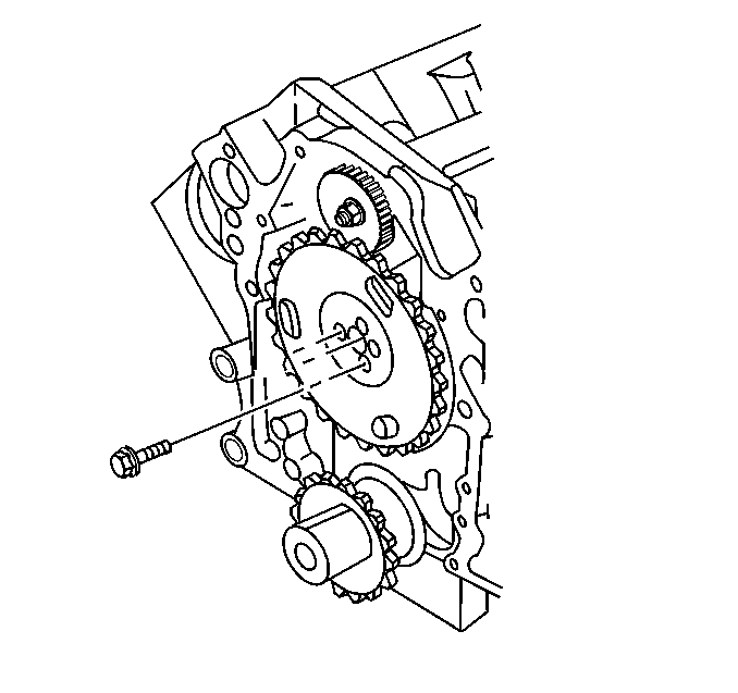
Refer to Valve Lifter Removal .
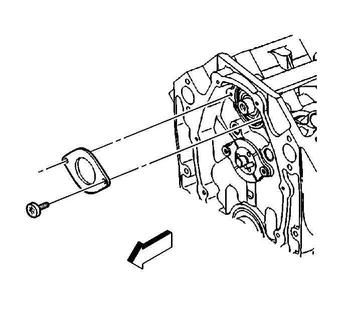
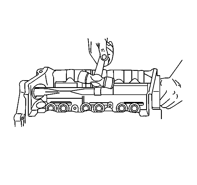
Important: The balance shaft and the front bearing are serviced only as a package. Do not remove the bearing from the balance shaft.
Refer to Balance Shaft Removal .
Refer to Balance Shaft Clean and Inspect .
Installation Procedure
Tools Required
| • | J 36660-A Torque/ Angle Meter |
| • | J 36996 Balance Shaft Installer |
| • | J 8092 Driver Handle |
- Use the J 8092 and the J 36660-A in order to install the balance shaft.
- Install the balance shaft retainer and the bolt.
- Install the balance shaft driven gear and the bolt.
- Install the drive gear onto the camshaft.
- Install the valve lifter retainer.
- Install the timing chain and the camshaft sprocket.
- Install the a/c condenser, if equipped.
- Install the radiator.
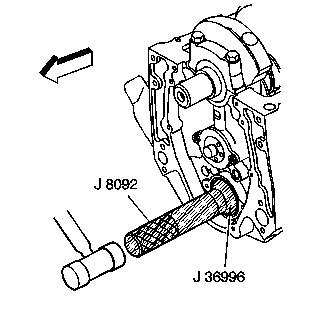
Refer to Balance Shaft Installation .
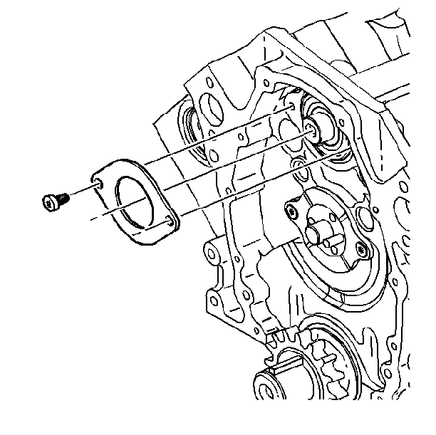
Refer to Balance Shaft Installation .
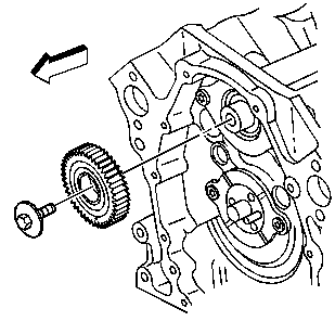
Refer to Balance Shaft Installation .
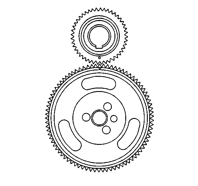
| • | Ensure that the timing marks on the balance shaft drive gears align. |
| • | The number four cylinder should be at the top dead center (TDC) of it's compression stroke. |
| • | The distributor rotor should face the number four terminal on the distributor cap. |
Refer to Valve Lifter Installation .
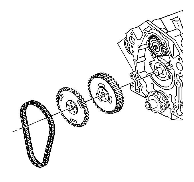
Refer to Timing Chain and Sprocket Replacement .

Refer to Condenser Replacement in HVAC.
Refer to Radiator Replacement in Engine Cooling.
