For 1990-2009 cars only
Repair Procedure
Tools Required
J 43653 Flywheel Holding Tool
- Disconnect the negative battery cable.
- Install the engine support fixture. Refer to Engine Support Fixture .
- Remove the front transmission mount bolts. Refer to Transmission Front Mount Replacement .
- Remove the splash shield. Refer to Wheelhouse Splash Shield Replacement in Body Front End.
- Remove the air cleaner and duct assembly from the throttle body. Refer to Air Cleaner Assembly Replacement in Engine Controls - 2.4L or Air Cleaner Assembly Replacement in Engine Controls - 3.4L.
- Remove the wire harness from the upper transaxle mount bracket.
- Remove the upper transaxle mount. Refer to Transmission Mount Replacement - Side .
- Remove the shifter cable. Refer to Transmission Control Replacement .
- Secure the vehicle radiator and condenser to the upper radiator support.
- Remove the ground cables from the engine block.
- Disconnect the PNP switch connector.
- Remove the upper bell housing bolts.
- Raise and support the vehicle. Refer to Lifting and Jacking the Vehicle in General Information.
- Support the vehicle with a safety stand.
- Drain the transaxle. Refer to Oil Pan Replacement in Automatic Transaxle 4T40-E/4T45-E.
- Remove the front suspension crossmember. Refer to Front Suspension Crossmember Replacement In Front Suspension.
- Remove the front tire and wheel assemblies. Refer to Tire and Wheel Removal and Installation in Tires and Wheels.
- Remove the following components:
- Remove the lower radiator and condenser support. Refer to Radiator Support in Body Front End.
- Remove the front transmission mount bracket bolts and bracket. Refer to Transmission Rear Mount Replacement .
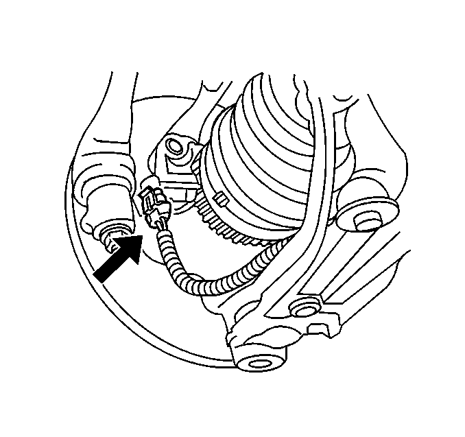
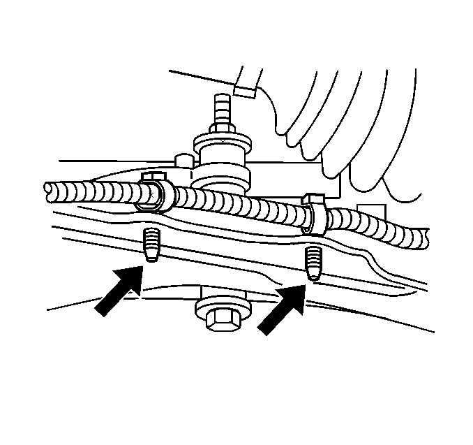
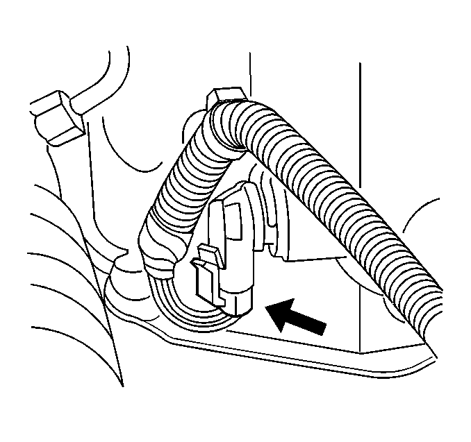
- Remove the front antilock brake system (ABS) wheel speed sensor (WSS) connectors.
- Unroute the ABS WSS harness.
- Remove the brake modulator assembly bolts and the brake modulator assembly. Refer to Brake Pressure Modulator Valve Assembly Replacement in Antilock Brake System.
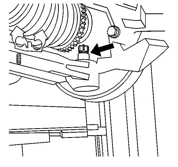
- Remove the vehicle speed sensor.
- Use J 43653 to remove the torque converter bolts. Refer to Flywheel to Torque Converter Bolt Replacement in Automatic Transaxle 4T40-E/4T45-E.
- Remove the left and right ball joint nuts.
- Separate the ball joint from the control arm. Refer to Lower Control Arm Ball Joint Replacement in Front Suspension.
- Remove the wheel drive shafts. Refer to Wheel Drive Shaft Replacement in Wheel Drive Shafts.
- Remove the front transaxle mount. Refer to Transmission Front Mount Replacement .
- Remove the ABS module. Refer to Brake Pressure Modulator Valve Assembly Replacement in Antilock Brake System.
- Separate the tie rod ends from the steering knuckles. Refer to Rack and Pinion Outer Tie Rod End Replacement in Power Steering System.
- Disconnect the power steering pressure line from the steering gear. Refer to Steering Linkage Inner Tie Rod Replacement in Power Steering System.
- Remove the brake lines from the retainer below the rack and pinion.
- Remove the steering column pinch bolt and position the intermediate shaft aside. Refer to Steering Gear Replacement in Power Steering System.
- Attach the transaxle case to the support stand.
- Remove the transaxle-to-engine mount bolts.
- Remove the lower 2 bell housing bolts and studs.
- Remove the transaxle:
- Flush the transmission cooler and lines. Refer to Transmission Fluid Cooler Flushing and Flow Test .
Caution: Refer to Battery Disconnect Caution in the Preface section.
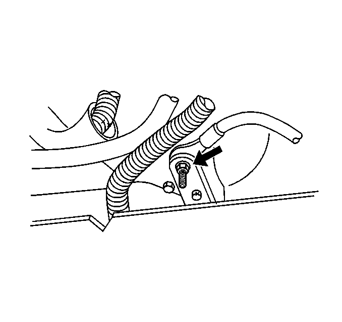
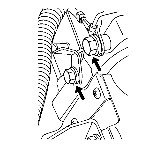
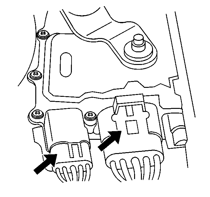
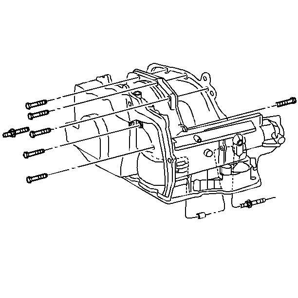
| • | The left front inner splash shield. Refer to Wheelhouse Splash Shield Replacement in Body Front End. |
| • | The right front inner splash shield. Refer to Wheelhouse Splash Shield Replacement in Body Front End. |
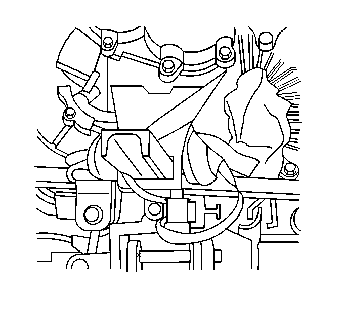
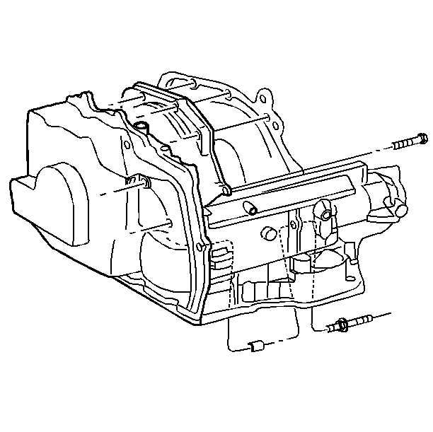
| 38.1. | Slide the transaxle away from the engine. |
| 38.2. | Carefully lower the support stand. |
Installation Procedure
- Install the transaxle:
- Install the lower transmission to engine bolts and 2 studs.
- Install the transaxle-to-engine mount bolts.
- Detach the transaxle case from the support stand.
- Install the steering column pinch bolt and position the intermediate shaft. Refer to Steering Gear Replacement in Power Steering System.
- Install the brake lines from the retainer below the rack and pinion.
- Connect the power steering pressure line to the rack and pinion. Refer to Steering Linkage Inner Tie Rod Replacement in Power Steering System.
- Install the tie rod ends to the steering knuckles. Refer to Rack and Pinion Outer Tie Rod End Replacement in Power Steering System.
- Install the ABS module. Refer to Brake Pressure Modulator Valve Assembly Replacement in Antilock Brake System.
- Install the front transaxle mount. Refer to Transmission Front Mount Replacement .
- Install the wheel drive shafts. Refer to Wheel Drive Shaft Replacement in Wheel Drive Shafts.
- Install the ball joint to the control arm. Refer to Lower Control Arm Ball Joint Replacement in Front Suspension.
- Install the left and right ball joint nuts.
- Install the torque converter bolts and flywheel cover bolts. Refer to Flywheel to Torque Converter Bolt Replacement .
- Install the vehicle speed sensor.
- Install the brake modulator assembly bolts and the brake modulator assembly. Refer to Brake Pressure Modulator Valve Assembly Replacement in Antilock Brake System.
- Install the front ABS/WSS connectors.
- Install the front transmission mount bracket bolts and bracket. Refer to Transmission Front Mount Replacement .
- Install the lower radiator and condenser support. Refer to Radiator Support in Body Front End.
- Install the following components:
- Install the front tire and wheel assemblies. Refer to Tire and Wheel Removal and Installation in Tires and Wheels.
- Install the upper bell housing bolts and studs.
- Lower the vehicle.
- Connect the PNP switch connector.
- Install the ground cables from the engine block.
- Secure the vehicle radiator and condenser to the upper radiator support.
- Install the shifter cable. Refer to Transmission Control Replacement .
- Install the upper transaxle mount. Refer to Transmission Rear Mount Replacement .
- Install the wire harness from the upper transaxle mount bracket.
- Install the air cleaner and duct assembly to the throttle body. Refer to Air Cleaner Assembly Replacement in Engine Controls - 2.4L or Air Cleaner Assembly Replacement in Engine Controls - 3.4L.
- Install the splash shield. Refer to Wheelhouse Splash Shield Replacement in Body Front End.
- Install the front transmission mount bolts. Refer to Transmission Front Mount Replacement .
- Remove the engine support fixture.
- Connect the negative battery cable.
- Fill the transmission with fluid. Refer to Transmission Fluid Check .
- Inspect the transaxle fluid level. Refer to Transmission Fluid Check .
- Reset the TAP values. Refer to Adapt Function .
| 1.1. | Slide the transaxle towards the engine. |
| 1.2. | Carefully raise the support stand. |
Notice: Refer to Fastener Notice in the Preface section.

Tighten
Tighten the bolts and studs to 90 N·m (66 lb ft).


| • | The left front inner splash shield. Refer to Wheelhouse Splash Shield Replacement in Body Front End. |
| • | The right front inner splash shield. Refer to Wheelhouse Splash Shield Replacement in Body Front End. |

Tighten
Tighten the bolts and studs to 90 N·m (66 lb ft).


Important: It is recommended that transmission adaptive pressure (TAP) information be reset.
Resetting the TAP values using a scan tool will erase all learned values in all cells. As a result, The ECM, PCM or TCM will need to relearn TAP values. Transmission performance may be affected as new TAP values are learned.