Front Side Door Trim Panel Replacement Pontiac
Removal Procedure
Caution: Unless directed otherwise, the ignition and start switch must be in the OFF or LOCK position, and all electrical loads must be OFF before servicing
any electrical component. Disconnect the negative battery cable to prevent an electrical spark should a tool or equipment come in contact with an exposed electrical terminal. Failure to follow these precautions may result in personal injury and/or damage to
the vehicle or its components.
- Disconnect the negative
battery cable.
Important: When removing a door trim panel or switch plate, disconnect the negative
battery terminal. This will eliminate the possibility of shorting out the
switch if you use a screwdriver, an awl, or other metal object in order
to remove the switch from the harness.
- Remove the front door warning reflector. Refer to
Front Side Door Warning Reflector Replacement
.
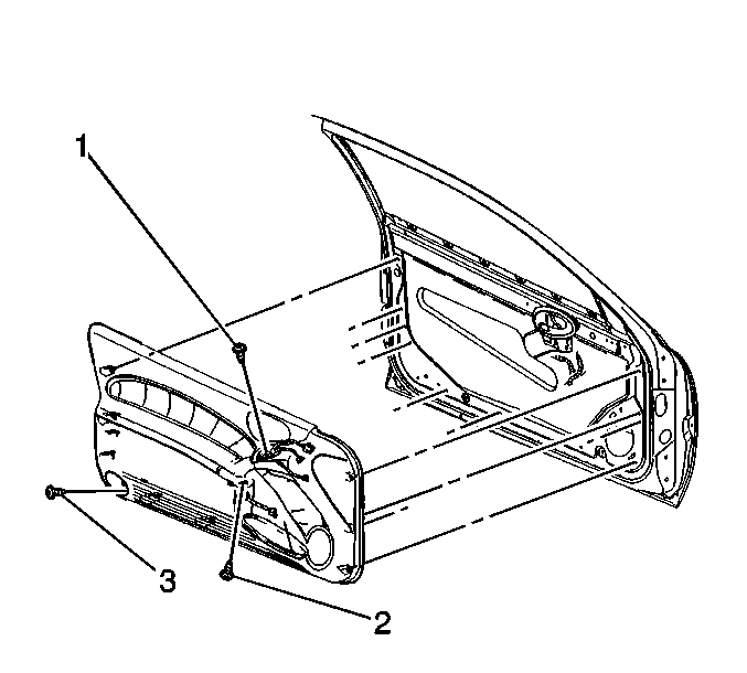
- Remove the door panel screw (3) through the hole in the
door warning reflector opening.
- Remove the screw (2) from the arm-rest pull handle.
- Use a flat-bladed tool in order to pry the front door switch bezel
assembly upward. Apply inboard pressure against the rear retaining clip.
- Disconnect:
| • | Power door lock switch connector, if equipped. |
| • | Power window switch, connector if equipped. |
| • | Power mirrior switch, connector if equipped (left side only). |
- Remove the front door switch bezel.
- Remove the door panel screw (1) through the switch bezel
opening.
- Remove the window regulator handle, if equipped. Refer to
Door Window Regulator Handle Replacement
.
- Use a flat bladed tool in order to remove the rear deck release
switch bezel.
- Disconnect the rear deck release switch connector.
- Gently disengage the door trim panel retaining clips.
- Remove the door trim panel from the door.
Installation Procedure
- Install the front door
trim panel to the door. Ensure that all of the trim panel retainers are secured.
- Install the inside door handle bezel. Refer to
Door Handle Bezel Replacement
.
- Connect the rear deck release connector.
- Install the rear deck release switch bezel. Press the bezel firmly
into place.
- Install the window regulator handle to the door. Refer to
Door Window Regulator Handle Replacement
.
Notice: Use the correct fastener in the correct location. Replacement fasteners
must be the correct part number for that application. Fasteners requiring
replacement or fasteners requiring the use of thread locking compound or sealant
are identified in the service procedure. Do not use paints, lubricants, or
corrosion inhibitors on fasteners or fastener joint surfaces unless specified.
These coatings affect fastener torque and joint clamping force and may damage
the fastener. Use the correct tightening sequence and specifications when
installing fasteners in order to avoid damage to parts and systems.
- Install the door trim panel screw (1)
through the switch bezel opening.
Tighten
Tighten the door trim panel screw to 10 N·m (89 lb in).
- Connect:
| • | Power door lock switch connector, if equipped. |
| • | Power window switch connector, if equipped. |
| • | Power mirror switch connector, if equipped. |
- Install the front door switch bezel assembly to the front door
trim panel.
- Install the door trim panel screw (2) to the arm-rest pull
handle.
Tighten
Tighten the door trim panel screw to 10 N·m (89 lb in).
- Install the door panel screw (3) through the hole in the
front door warning reflector.
Tighten
Tighten the door trim panel screw to 10 N·m (89 lb in).
- Install the front door warning reflector. Refer to
Front Side Door Warning Reflector Replacement
.
- Connect the negative battery cable.
Front Side Door Trim Panel Replacement Oldsmobile
Removal Procedure
Caution: Unless directed otherwise, the ignition and start switch must be in the OFF or LOCK position, and all electrical loads must be OFF before servicing
any electrical component. Disconnect the negative battery cable to prevent an electrical spark should a tool or equipment come in contact with an exposed electrical terminal. Failure to follow these precautions may result in personal injury and/or damage to
the vehicle or its components.
- Disconnect the negative battery cable.
Important: When removing a door trim panel or switch plate, disconnect the negative
battery terminal. This will eliminate the possibility of shorting out the
switch if you use a screwdriver, an awl, or other metal object in order
to remove the switch from the harness.
- Remove the window regulator handle, if equipped. Refer to
Door Window Regulator Handle Replacement
.
- Remove the front door warning reflector. Refer to
Front Side Door Warning Reflector Replacement
.
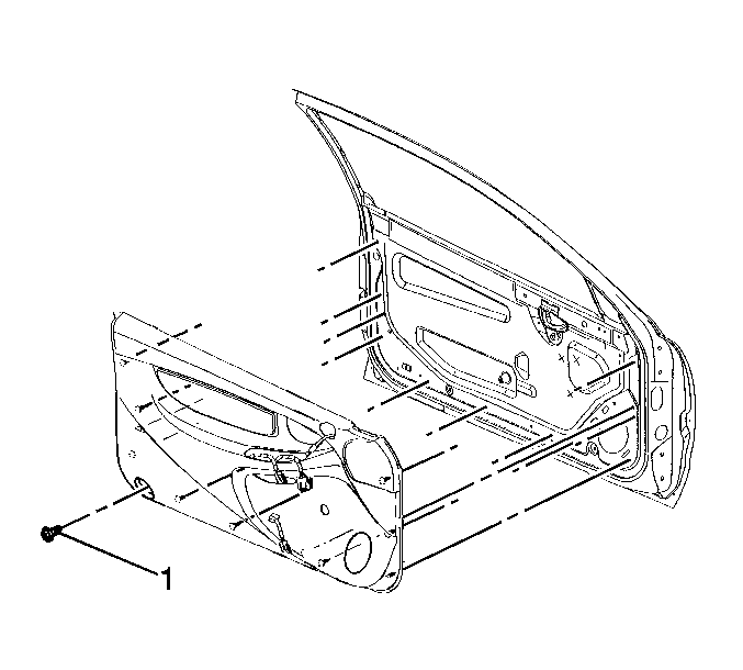
- Remove the door panel screw (1) through the hole in the
door warning reflector opening.
- Use a flat bladed tool in order to remove the rear deck release
switch bezel.
- Disconnect the rear deck release switch.
- Use a flat-bladed tool in order to remove the lower switch bezel
trim screw access cover.
- Remove the lower switch bezel trim screws.
- Remove the lower switch bezel trim panel.
- Use a flat-bladed tool in order to pry the front door switch bezel
upward.
- Disconnect:
| • | Power door lock switch connector, if equipped. |
| • | Power window switch connector, if equipped. |
| • | Power mirror switch connector, if equipped (left side only). |
- Gently disengage the front door trim retaining clips and remove
the door trim panel from the door.
Installation Procedure
- Install the front door trim panel to the door. Ensure that the retainers
are locked into place.
- Connect the rear deck release connector.
- Install the rear deck release switch bezel. Press the bezel firmly
into place.
- Install the window regulator handle to the door. Refer to
Door Window Regulator Handle Replacement
.
- Connect:
| • | Power door lock switch connector, if equipped. |
| • | Power window switch connector, if equipped. |
| • | Power mirror switch connector, if equipped. |
- Install the front door switch bezel assembly to the front door
trim panel.
- Install the lower switch bezel trim panel.
Notice: Use the correct fastener in the correct location. Replacement fasteners
must be the correct part number for that application. Fasteners requiring
replacement or fasteners requiring the use of thread locking compound or sealant
are identified in the service procedure. Do not use paints, lubricants, or
corrosion inhibitors on fasteners or fastener joint surfaces unless specified.
These coatings affect fastener torque and joint clamping force and may damage
the fastener. Use the correct tightening sequence and specifications when
installing fasteners in order to avoid damage to parts and systems.
- Install the lower
switch bezel trim screws.
Tighten
Tighten the lower switch bezel trim screws to 10 N·m (89
lb in).
- Install the lower switch bezel trim screw access cover.
- Install the door trim panel screw (1) through the hole
in the front door warning reflector.
Tighten
Tighten the door trim panel screw (1) to 10 N·m
(89 lb in).
- Install the front door warning reflector. Refer to
Front Side Door Warning Reflector Replacement
.
- Connect the negative battery cable.
