For 1990-2009 cars only
Power Vacuum Brake Booster Replacement L47
Removal Procedure
- Place the vehicle on a level surface.
- Block the front wheels.
- Apply the park brake.
- Shift the vehicle into low gear.
- Remove the left closeout insulator panel. Refer to Instrument Panel Insulator Panel Replacement - Left Side in Instrument Panel, Gages, and Console.
- Remove the left knee bolster. Refer to Knee Bolster Replacement in Instrument Panel, Gages and Console.
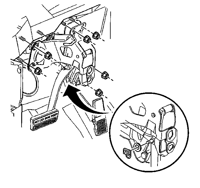
- Remove the retainer clip for the from the brake pedal clevis pin.
- Remove the foam spacer from the brake pedal clevis pin.
- Disconnect the vacuum brake booster pushrod from the brake pedal clevis pin.
- Remove the brake pedal to booster mounting nuts.
- Remove the air cleaner assembly. Refer to Air Cleaner Assembly Replacement in Engine Controls - 4.0L.
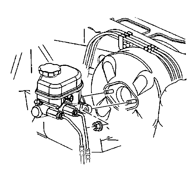
- Remove the master cylinder from the vacuum brake booster. Refer to Master Cylinder Replacement and carefully position the master cylinder out of the way. Do not disconnect the hydraulic brake pipes.
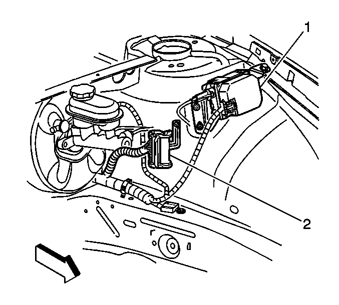
- Remove the cruise control module (1) and position out of the way. Refer to Cruise Control Module Replacement in Cruise Control.
- Disconnect the electrical connector (2) at the left strut tower. Refer to Master Electrical Component List in Engine Electrical.
- Remove the accelerator control cable bracket from the throttle body and position the cables and bracket out of the way. Refer to Accelerator Control Cable Bracket Replacement in Engine Mechanical - 4.0L.
- Remove the left carpet retainer. Refer to Front Carpet Retainer Replacement in Interior Trim.
- Disconnect the shift control cable from the shaft lever pin. Refer to Range Selector Lever Cable Replacement in Automatic Transaxle - 4T80 - E.
- Remove the shift control cable and bracket and position out of the way. Refer to Range Selector Lever Cable Replacement in Automatic Transaxle - 4T80 - E.
- Disconnect the vacuum brake check valve and hose as an assembly from the vacuum brake booster.
- Remove the inlet heater pipe. Refer to Heater Inlet Pipe Replacement in Heating, Ventilation and Air Conditioning.
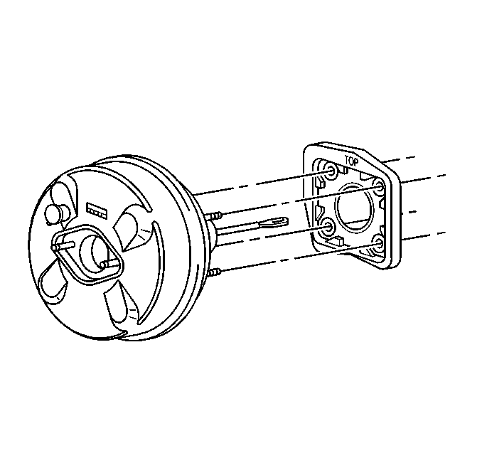
- Remove the vacuum brake booster from the vehicle.
- Remove the vacuum brake booster mounting gasket, if gasket replacement is necessary.


Installation Procedure
- Install the brake booster mounting gasket to booster, if removed previously.
- Install the vacuum brake booster to the vehicle.
- Install the vacuum brake booster pushrod to the brake pedal clevis pin.
- Install the foam spacer to the brake pedal clevis pin.
- Install the retaining clip to the brake pedal clevis pin.
- Install the booster stud mounting nuts to the booster studs.
- Install the left knee bolster. Refer to Knee Bolster Replacement in Instrument Panel, Gages, and Console.
- Install the left closeout insulator panel. Refer to Instrument Panel Insulator Panel Replacement - Left Side in Instrument Panel, Gages, and Console.
- Install the left carpet retainer. Refer to Front Carpet Retainer Replacement in Interior Trim.
- Install the inlet heater pipe. Refer to Heater Inlet Pipe Replacement in Heating, Ventilation and Air Conditioning.
- Install the shift control cable and bracket. Refer to Range Selector Lever Cable Replacement in Automatic Transaxle - 4T80 - E.
- Connect the shift control cable to the shaft lever pin. Refer to Range Selector Lever Cable Replacement in Automatic Transaxle - 4T80 - E.
- Shift the vehicle into park.
- Install the master cylinder to the vacuum brake booster. Refer to Master Cylinder Replacement .
- Install the master cylinder mounting nuts.
- Reposition and connect the vacuum check valve to the vacuum brake booster.
- Connect the electrical connector (2) to the left strut tower. Refer to Master Electrical Component List in Engine Electrical.
- Install the cruise control module. Refer to Accelerator Control Cable Bracket Replacement in Cruise Control.
- Install the accelerator control cables and bracket. Refer to Accelerator Control Cable Bracket Replacement in Engine Controls- 4.0L.
- Install the air cleaner assembly. Refer to Air Cleaner Assembly Replacement in Engine Controls- 4.0L.
- Remove the blocks from the front wheels.
- Release the park brake.


Notice: Refer to Fastener Notice in the Preface section.
Tighten
Tighten the brake pedal to booster stud mounting nuts to 23 N·m
(17 lb ft).

Tighten
Tighten the master cylinder mounting nuts to 25 N·m (18 lb ft).

