Removal Procedure
- Set the parking brakes and block the wheels.
- Open the console storage lid.
- Ensure the cup holder is in the open position.
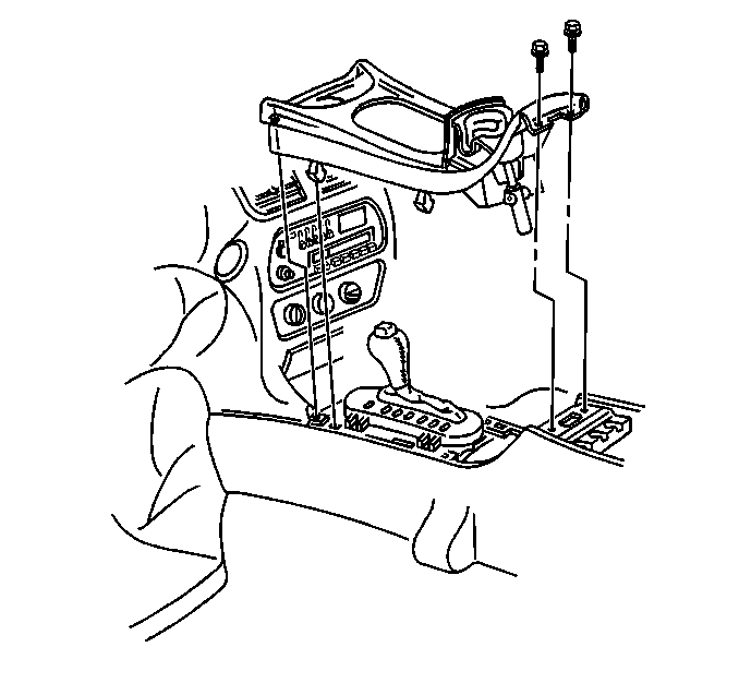
- Remove the front floor console trim plate bolts.
- Remove the front floor console trim plate.
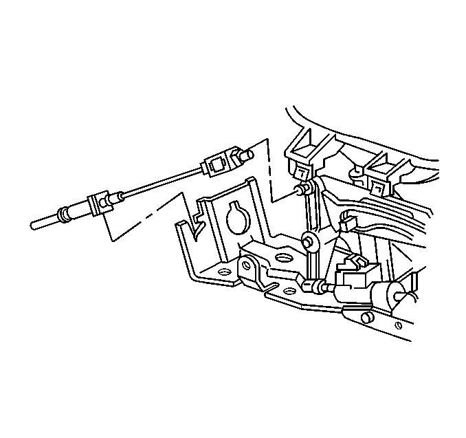
- Disconnect and remove the park lock cable from the console shift control and bracket.
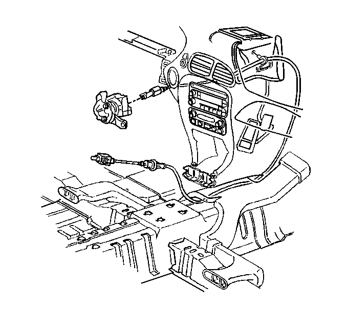
- Remove the park lock cable from beneath the heater duct.
- Remove the park lock cable from behind the accelerator pedal linkage and accelerator pedal bracket.
- Disconnect the park lock cable from the pedal bracket.
- Remove the steering column opening filler and knee bolster bracket in order to gain access to the bottom of the ignition switch. Refer to Knee Bolster Bracket Replacement in Instrument Panel, Gauges and Console.
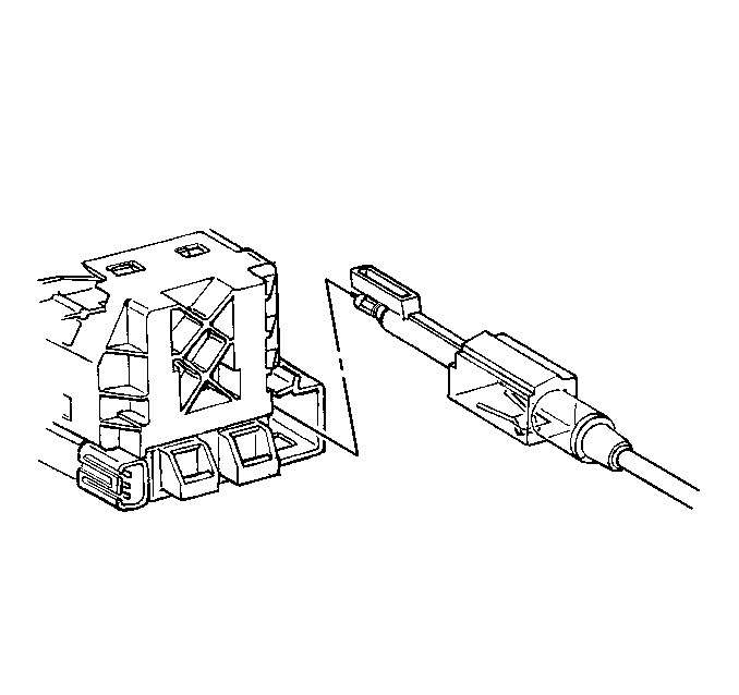
- Place the ignition switch in the ACC position.
- Depress the tab in order to unlock the park lock cable from the ignition switch.
- Disconnect and remove the park lock cable.


Installation Procedure
- Place the ignition switch in the ACC position.
- Install and connect the park lock cable to the ignition switch.
- Connect the park lock cable to the pedal bracket.
- Install and route the park lock cable behind the accelerator pedal linkage and accelerator pedal bracket.
- Install and route the park lock cable beneath the heater duct.
- Install and connect the park lock cable to the console shift control and bracket.
- Verify the function of the park lock system. Refer to Park Lock Cable Adjustment Park Lock Cable Adjustment.
- Install the steering column opening filler and knee bolster bracket. Refer to Knee Bolster Bracket Replacement Body and Accessories.
- Install the front floor console trim plate.
- Install the front floor console trim plate bolts.
- Close the console storage lid.
- Release the parking brakes and unblock the wheels.


Important: Do not bend the cable less than a 102.00 mm (4 in) radius during installation, the cable is not to be kinked or damaged.


Important: The cup holder must be in the open position in order to install the front floor console trim plate.
Notice: Use the correct fastener in the correct location. Replacement fasteners must be the correct part number for that application. Fasteners requiring replacement or fasteners requiring the use of thread locking compound or sealant are identified in the service procedure. Do not use paints, lubricants, or corrosion inhibitors on fasteners or fastener joint surfaces unless specified. These coatings affect fastener torque and joint clamping force and may damage the fastener. Use the correct tightening sequence and specifications when installing fasteners in order to avoid damage to parts and systems.
Tighten
Tighten the front floor console trim plate bolts to 2 N·m
(14 lb in).
