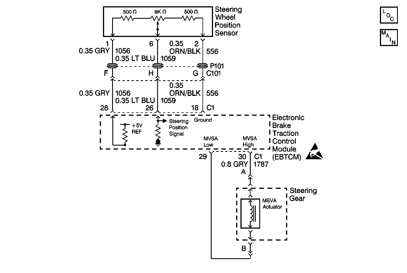
Circuit Description
The Variable Effort Steering (VES) Diagnostic System Check is an organized approach to identify problems associated with the Magnetic Steering Variable Assist (MSVA) system also known as MAGNASTEER®. The MSVA system varies the driver effort required to steer as the vehicle speed changes. At low speeds, the system requires minimum steering effort for easy turning and parking maneuvers. Steering effort is increased at higher speeds in order to provide the driver with firmer steering (road feel) and directional stability. MSVA accomplishes this by adding or subtracting torque in the rotary input shaft to the power rack and pinion. When the vehicle is stationary, MSVA adds torque to assist the driver in turning the steering wheel. As the vehicle speed increases, the torque provided by MSVA decreases. MSVA increases resistance to the turning of the steering wheel for improved road feel at higher speeds. The Electronic Brake and Traction Control Module (EBTCM) controls the current to the MSVA actuator to increase or decrease the torque provides by the actuator. The EBTCM uses the inputs from the ABS wheel speed sensors and the Steering Wheel Position Sensor to calculate the amount of torque applied by the MSVA actuator.
Diagnostic Aids
| • | The Diagnostic Trouble Codes (DTCs) are stored in the EBTCM for the MSVA if a malfunction occurs. No warning lamp will come on during the malfunction. When a malfunction occurs, the DTC(s) can be retrieved using a scan tool. A difference in power steering effort may be felt if a MSVA DTC exists. |
| • | It is very important that a thorough inspection of the wiring and connectors be performed. Failure to carefully and fully inspect wiring and connectors may result in misdiagnosis, causing part replacement with reappearance of the malfunction. |
| • | Inspect all of the circuitry that may cause the intermittent complaint for the following conditions: |
| - | Broken wire inside the insulation |
| - | Backed out terminals |
| - | Improper mating |
| - | Improperly formed terminals |
| - | Damaged terminals |
| - | Poor terminal to wiring connections |
| - | Physical damage to the wiring harness |
| • | If an intermittent malfunction exists refer to General Electrical Diagnosis in Wiring Systems. |
Step | Action | Value(s) | Yes | No |
|---|---|---|---|---|
1 |
Does the scan tool communicate with the Electronic Brake and Traction Control Module (EBTCM)? | -- | Go to Diagnostic System Check - Data Link Communications in Data Link Communications | |
2 | Using the scan tool in the ABS Diagnostic Trouble Codes (DTC), read the VES DTCs. Does the scan tool display a current or history VES DTC(s)? | -- | Go to Diagnostic Trouble Code (DTC) List for the Applicable DTC Table | |
3 | Are there any current or history ABS/TCS DTC(s) displayed ? | -- | Go to Diagnostic System Check - ABS in Antilock Brake System - Bosch 5.3 or Diagnostic System Check - ABS in Antilock Brake System - Delco VI | |
4 |
Does the steering wheel turn with little effort? | -- | Go to Steering Effort Hard in One or Both Directions in Power Steering System | |
5 |
Was there any rattle and/or chuckle noise from the vehicle? | -- | Go to Rattle or Chuckle Noise in Steering Gear in Power Steering System | System OK |
