Generator Replacement 3.5L Twin Cam V6 LX5
Removal Procedure
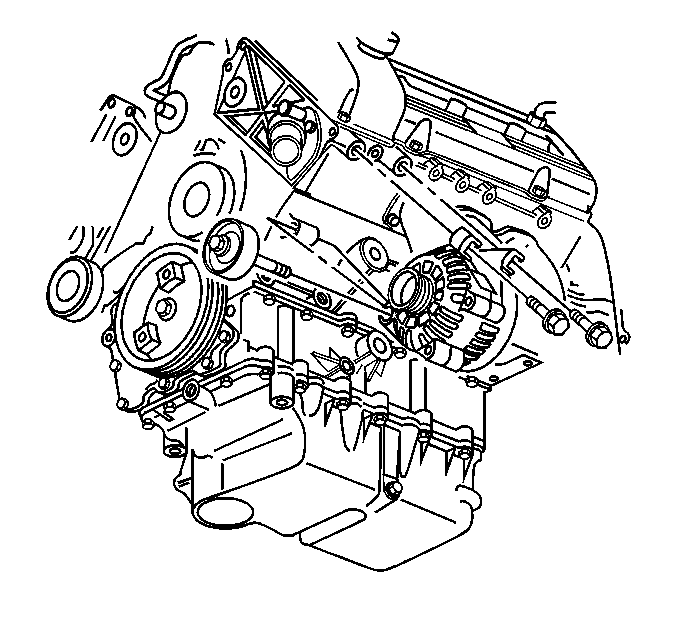
The Delphi AD237 (KG7) generator is serviced as a complete unit only.
- Disconnect the battery ground (negative) cable. Refer to Battery Negative Cable Disconnection and Connection .
- Remove the drive belt. Refer to Drive Belt Replacement in Engine Mechanical - 3.5L.
- Drain the engine coolant. Refer to Cooling System Draining and Filling in Engine Cooling.
- Remove the battery tray. Refer to Battery Tray Replacement .
- Remove the engine cooling fan assembly. Refer to Engine Cooling Fan Replacement in Engine Cooling.
- Remove the thermostat housing and the radiator hose. Refer to Engine Coolant Thermostat Replacement in Engine Cooling.
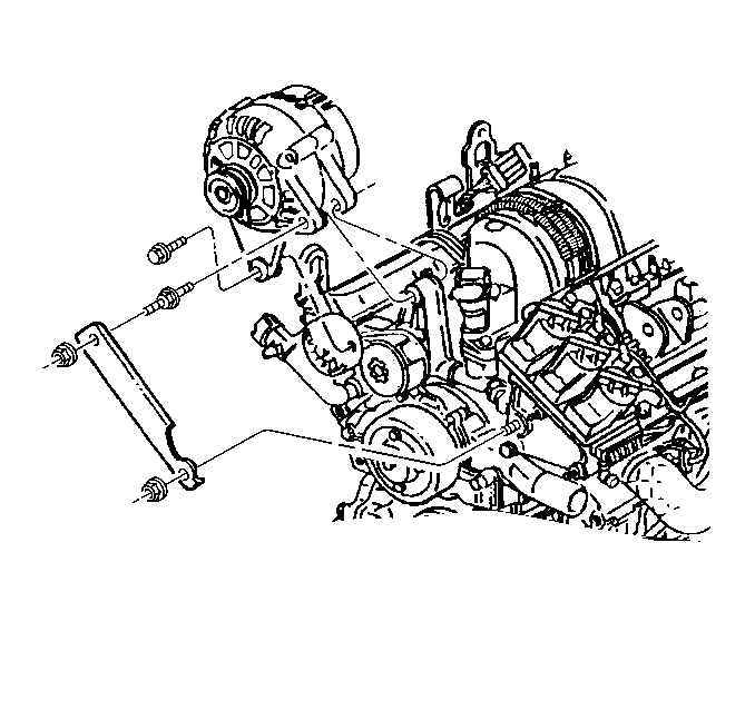
- Remove the outboard generator bolt.
- Loosen the inboard generator bolt.
- Remove the idler pulley bolt and the idler pulley.
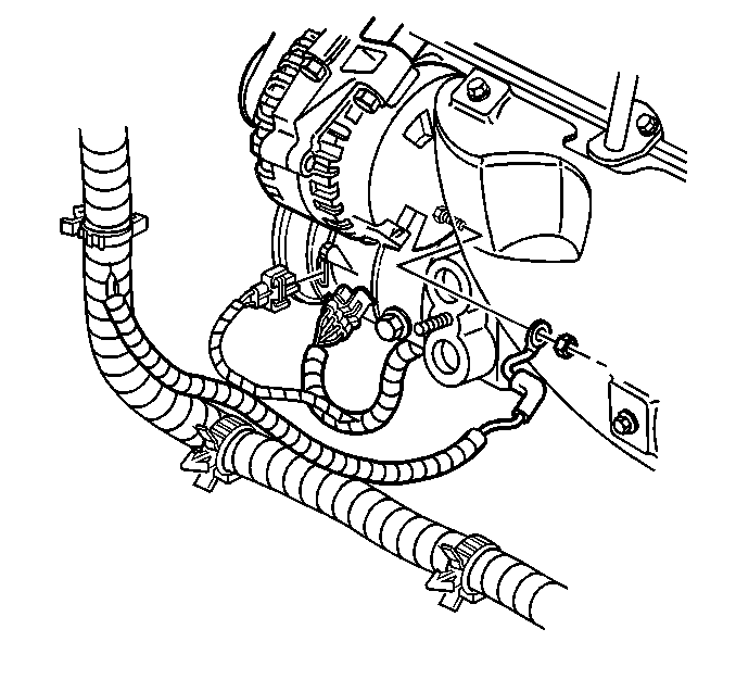
- Disconnect the wiring harness connector from the generator.
- Reposition the protective boot from the generator output BAT terminal for access.
- Remove the generator output BAT terminal nut and disconnect the battery (positive) lead from the generator.
- Remove the generator.


Installation Procedure
- Position the generator to the engine.
- Connect the wiring harness connector to the generator.
- Connect the battery (positive) lead and install the generator output BAT terminal nut.
- Press the protective boot on to the generator output BAT terminal.
- Place the outboard generator bolt into the generator housing.
- Position the generator on the inboard generator bolt and finger tighten the outboard bolt.
- Install the idler pulley and idler pulley bolt.
- Tighten the bolts in the order described. The following is a mandatory torque sequence:
- Install the battery tray. Refer to Battery Tray Replacement .
- Install the thermostat housing and the radiator hose. Refer to Engine Coolant Thermostat Replacement in Engine Cooling.
- Install the engine cooling fan assembly. Refer to Engine Cooling Fan Replacement in Engine Cooling.
- Fill the engine with engine coolant. Refer to Cooling System Draining and Filling in Engine Cooling.
- Install the drive belt. Refer to Drive Belt Replacement in Engine Mechanical - 3.5L.
- Connect the battery ground (negative) cable. Refer to Battery Negative Cable Disconnection and Connection .

Notice: Use the correct fastener in the correct location. Replacement fasteners must be the correct part number for that application. Fasteners requiring replacement or fasteners requiring the use of thread locking compound or sealant are identified in the service procedure. Do not use paints, lubricants, or corrosion inhibitors on fasteners or fastener joint surfaces unless specified. These coatings affect fastener torque and joint clamping force and may damage the fastener. Use the correct tightening sequence and specifications when installing fasteners in order to avoid damage to parts and systems.
Tighten
Tighten the generator output BAT terminal nut to 20 N·m
(15 lb ft).
Notice: Ensure the proper bolts for mounting the A/C compressor and/or the generator are being installed. The mounting bolts for the A/C compressor and the generator are very similar. The A/C compressor mounting bolts have an overall length of approximately 74 mm (2.9 in). The generator mounting bolts have an overall length of approximately 69 mm (2.7 in). Installation of the generator using the longer A/C compressor mounting bolts will result in internal damage to the cylinder head and engine coolant leakage.

| 8.1. | Tighten the idler pulley bolt. |
Tighten
Tighten the idler pulley bolt to 50 N·m (37 lb ft).
| 8.2. | Tighten the generator bolts. |
Tighten
Tighten the generator bolts to 50 N·m (37 lb ft).
Generator Replacement 3800 V6 L36
Removal Procedure
The Delphi CS130D (K68) generator is serviced as a complete unit only.
- Disconnect the battery ground (negative) cable. Refer to Battery Negative Cable Disconnection and Connection .
- Remove the drive belt from the generator. Refer to Drive Belt Replacement in Engine Mechanical - 3.8L.
- Remove the rear generator brace bolt. Refer to Generator Brace Replacement .
- Remove the bolts from the generator.
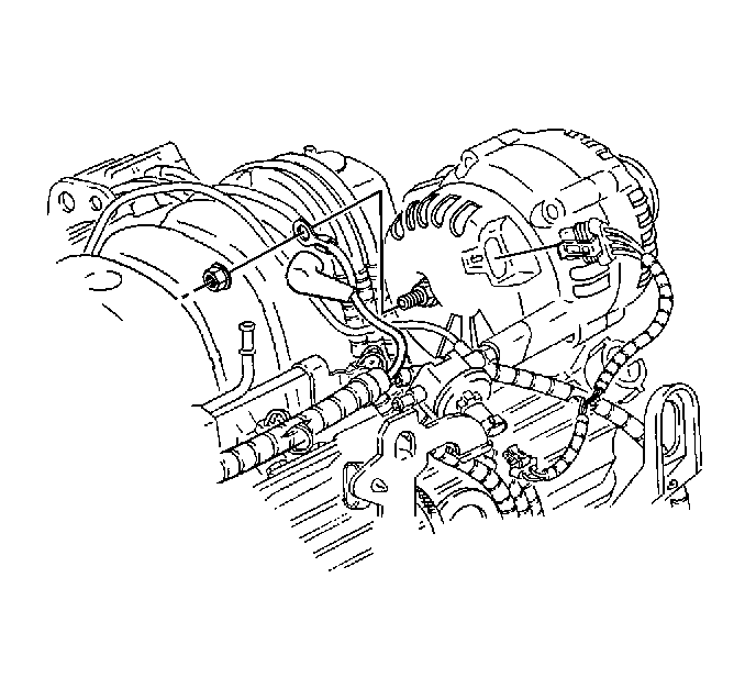
- Remove the wiring harness connector from the generator.
- Remove the protective boot from the generator output BAT terminal for access.
- Remove the generator output BAT terminal nut and the battery (positive) lead from the generator.
- Remove the generator.


Installation Procedure
- Place the generator to the engine.
- Install the battery (positive) lead and the generator output BAT terminal nut.
- Press the protective boot on to the generator output BAT terminal.
- Install the wiring harness connector to the generator.
- Finger start the generator rear bracket bolt to the hole on generator bracket. Do not tighten the bolt.
- Finger start the generator stud to the hole on the generator bracket. Do not tighten the bolt.
- Place the generator to the generator bracket on the engine.
- Install the generator bolt. Do not tighten the bolt.
- Tighten the generator bolts in the order described. The following is a mandatory torque sequence:
- Install the drive belt to the generator. Refer to Drive Belt Replacement in Engine Mechanical - 3.8L.
- Connect the battery ground (negative) cable. Refer to Battery Negative Cable Disconnection and Connection .

Notice: Use the correct fastener in the correct location. Replacement fasteners must be the correct part number for that application. Fasteners requiring replacement or fasteners requiring the use of thread locking compound or sealant are identified in the service procedure. Do not use paints, lubricants, or corrosion inhibitors on fasteners or fastener joint surfaces unless specified. These coatings affect fastener torque and joint clamping force and may damage the fastener. Use the correct tightening sequence and specifications when installing fasteners in order to avoid damage to parts and systems.
Tighten
Tighten the generator output BAT terminal nut to 20 N·m
(15 lb ft).

| 9.1. | Tighten the generator bolt. |
Tighten
Tighten the generator bolt to 50 N·m (37 lb
ft).
| 9.2. | Tighten the generator stud. |
Tighten
Tighten the generator stud to 30 N·m (22 lb
ft).
| 9.3. | Tighten the rear generator brace bolt. Refer to Generator Brace Replacement . |
Tighten
Tighten the rear generator brace bolt to 50 N·m (37 lb ft).
