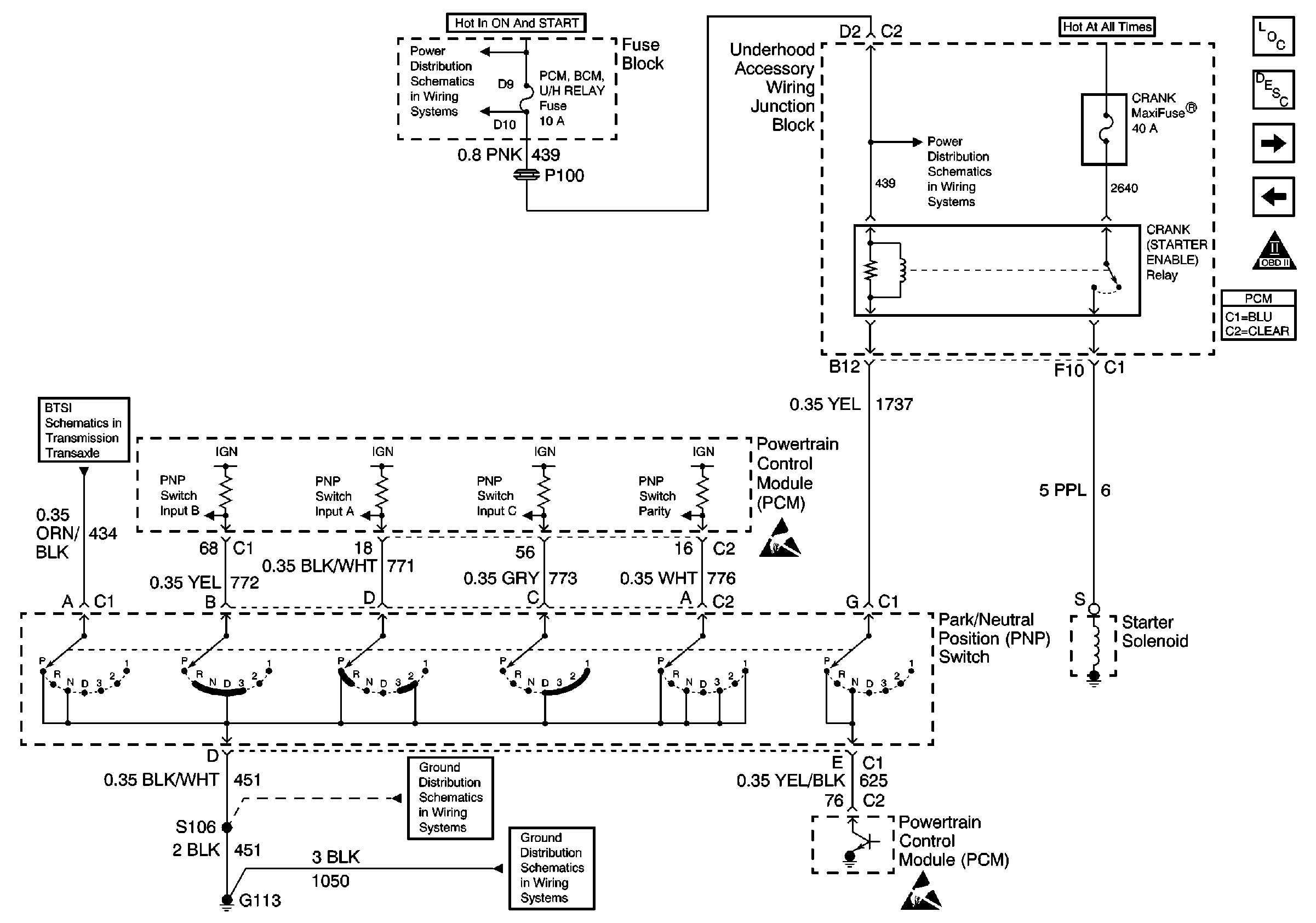
| Table 1: | Starter Enable (Crank) Relay |
Refer to
Transaxle Range Switch Outputs

in Engine Controls Schematics.
Circuit Description
This relay is labelled as Crank Relay in the Underhood Accessory Wiring Junction Block.
Ignition voltage is supplied directly to the Starter Enable (Crank) relay. The relay control circuit is connected through the Transaxle Range switch to the PCM. The Transaxle Range switch must be in the Park or Neutral position for the PCM to operate the relay. The powertrain control module (PCM) controls the relay by grounding the control circuit via an internal solid state device called a driver. The primary function of the driver is to supply the ground for the component being controlled. Each driver has a fault line which is monitored by the PCM. When the PCM is commanding a component on, the voltage of the control circuit should be near 0 volts. When the PCM is commanding the control circuit to a component off, the voltage potential of the circuit should be near battery voltage. The status of the driver can be monitored using a scan tool. If the fault detection circuit senses a voltage other than what is expected, the driver status will change from OK to Fault.
The PCM will monitor the control circuit for the following:
| • | A short to ground |
| • | A short to voltage |
| • | An open circuit |
| • | An open relay coil |
| • | An internally shorted or excessively low resistance relay coil |
Diagnostic Aids
Use the J 35616 connector test adapter kit for any test that requires probing the PCM harness connectors, electrical center fuse/relay cavities, component terminals or a component harness connector. Using this kit will prevent damage caused by improper probing of connector terminals.
If the problem is intermittent, refer to Intermittent Conditions for diagnosis.
Relay Terminal Identification
Use the following relay cavity table in order to locate the correct cavities to probe during diagnosis. The table layout corresponds to the cavity layout in the underhood accessory junction block. Four blade relays can be inserted 2 ways. Use the table and NOT the numbering on the relay to avoid probing incorrectly.
Top of Junction Block | |
|---|---|
Switch Power (crank MaxiFuse) | Coil Ground (PCM) |
Coil Power (fuse) | Switch Load (starter) |
Test Description
The number below refers to the step number on the diagnostic table.
Step | Action | Value(s) | Yes | No |
|---|---|---|---|---|
1 | Did you perform the PCM Controlled Starter Diagnosis? | -- | Go to Powertrain Control Module Controlled Starter Diagnosis | |
2 |
Is the test lamp off with the key in On, and on with the key in Start? | -- | ||
3 |
Does the test lamp illuminate? | -- | ||
4 | Probe the control circuit to the relay coil in the relay harness connector with the test lamp connected to B+. Does the test lamp illuminate? | -- | ||
5 |
Does the test lamp illuminate? | -- | ||
6 |
Does the test lamp illuminate? | -- | ||
7 | Test the circuit between the transaxle range switch and the PCM for an open or short to power. Refer to Wiring Repairs in Wiring Systems. Was a problem found and corrected? | -- | ||
8 | Check for poor connections and terminal tension at the relay harness connector. Refer to Testing for Intermittent Conditions and Poor Connections in Wiring Systems . Was a problem found and corrected? | -- | ||
9 | Repair the relay control circuit. Refer to Wiring Repairs in Wiring Systems. Is the action complete? | -- | -- | |
10 | Repair the ignition feed circuit to the relay coil. Refer to Wiring Repairs in Wiring Systems. Is the action complete? | -- | -- | |
11 | Replace the relay. Is the action complete? | -- | -- | |
12 | Check for poor connections and terminal tension at the transaxle range switch harness connector. Refer to Testing for Intermittent Conditions and Poor Connections in Wiring Systems. Was a problem found and corrected? | -- | ||
13 | Replace the transaxle range switch. Refer to Park/Neutral Position Switch Replacement in Automatic Transmission 4T 65E. Is the action complete? | -- | -- | |
14 | Check for poor connections and terminal tension at the PCM harness connector. Refer to Testing for Intermittent Conditions and Poor Connections in Wiring Systems. Was a problem found and corrected? | -- | ||
|
Important: The replacement PCM must be programmed. Replace the PCM. Refer to Powertrain Control Module Replacement/Programming . Is the action complete? | -- | -- | ||
16 |
Does the scan tool indicate that this test ran and passed? | -- | ||
17 | Review the captured data using the scan tool. Are there any DTCs that have not been diagnosed? | -- | Go to the applicable DTC table | System OK |
