For 1990-2009 cars only
Tools Required
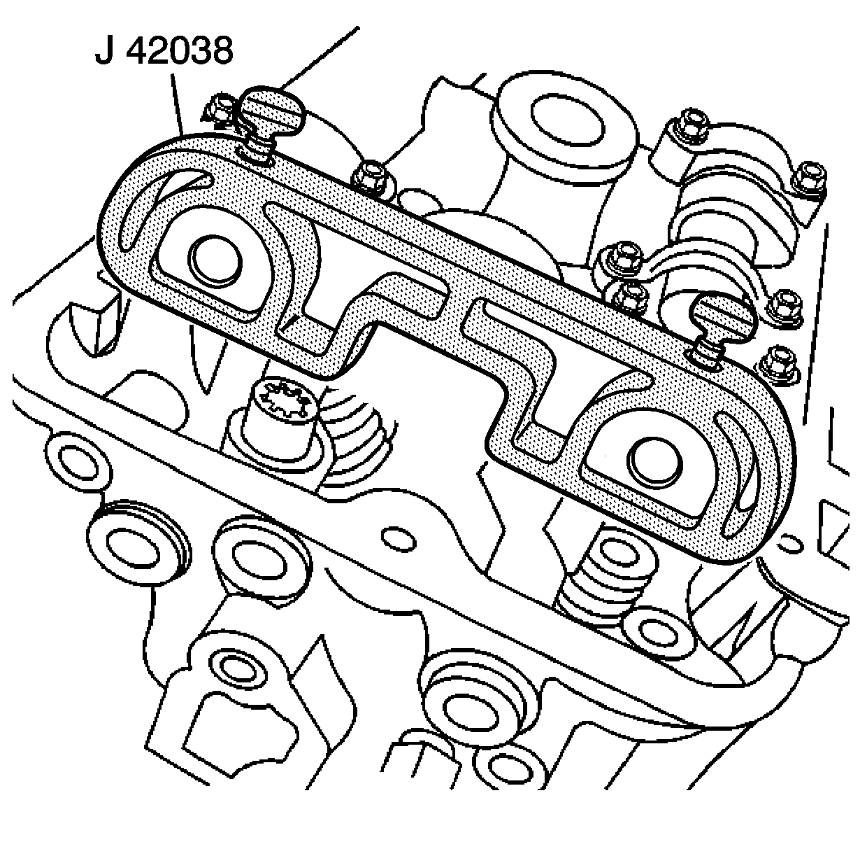
J 42038 Camshaft Holding Fixtures
Removal Procedure
- Remove the engine front cover. Refer to Engine Front Cover Replacement .
- Remove the camshaft covers. Refer to Camshaft Cover Replacement .
- Install the camshaft holding fixture J 42038 onto the ends of the camshaft. Rotate the engine to align the camshafts with the tool using the hex in the camshaft and an open wrench.
- When installed properly, the J 42038 will be fully seated on the camshaft ends with the camshaft flats parallel to the cam cover sealing surface.
- Remove the oil pan. Refer to Oil Pan Replacement .
- Remove the oil pump pipe and screen. Refer to Oil Pump Suction Pipe and Screen Assembly Replacement .
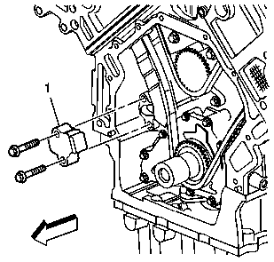
- Remove the camshaft drive chain tensioner (1) in order to remove the primary camshaft drive chain from the drive sprocket. Refer to Camshaft Drive Chain Tensioner Replacement .
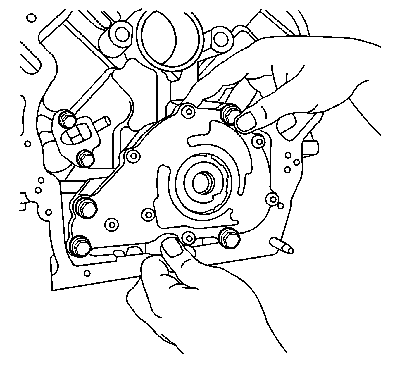
- Remove the four oil pump assembly retaining bolts identified by the larger head size.
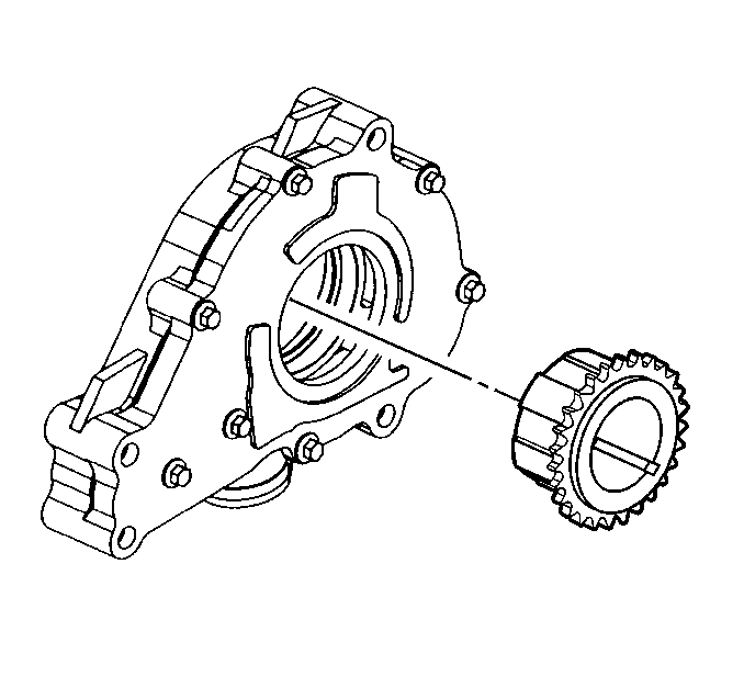
- Slide the oil pump assembly off the nose of the crankshaft with the drive sprocket in place.
- Remove the crankshaft sprocket from the oil pump assembly.
- Wrap the oil pump in a towel for safe, clean storage until inspection or assembly is necessary.
- If necessary, disassemble the oil pump. Refer to Oil Pump Disassemble .
- If necessary, clean and inspect the oil pump. Refer to Oil Pump Cleaning and Inspection .
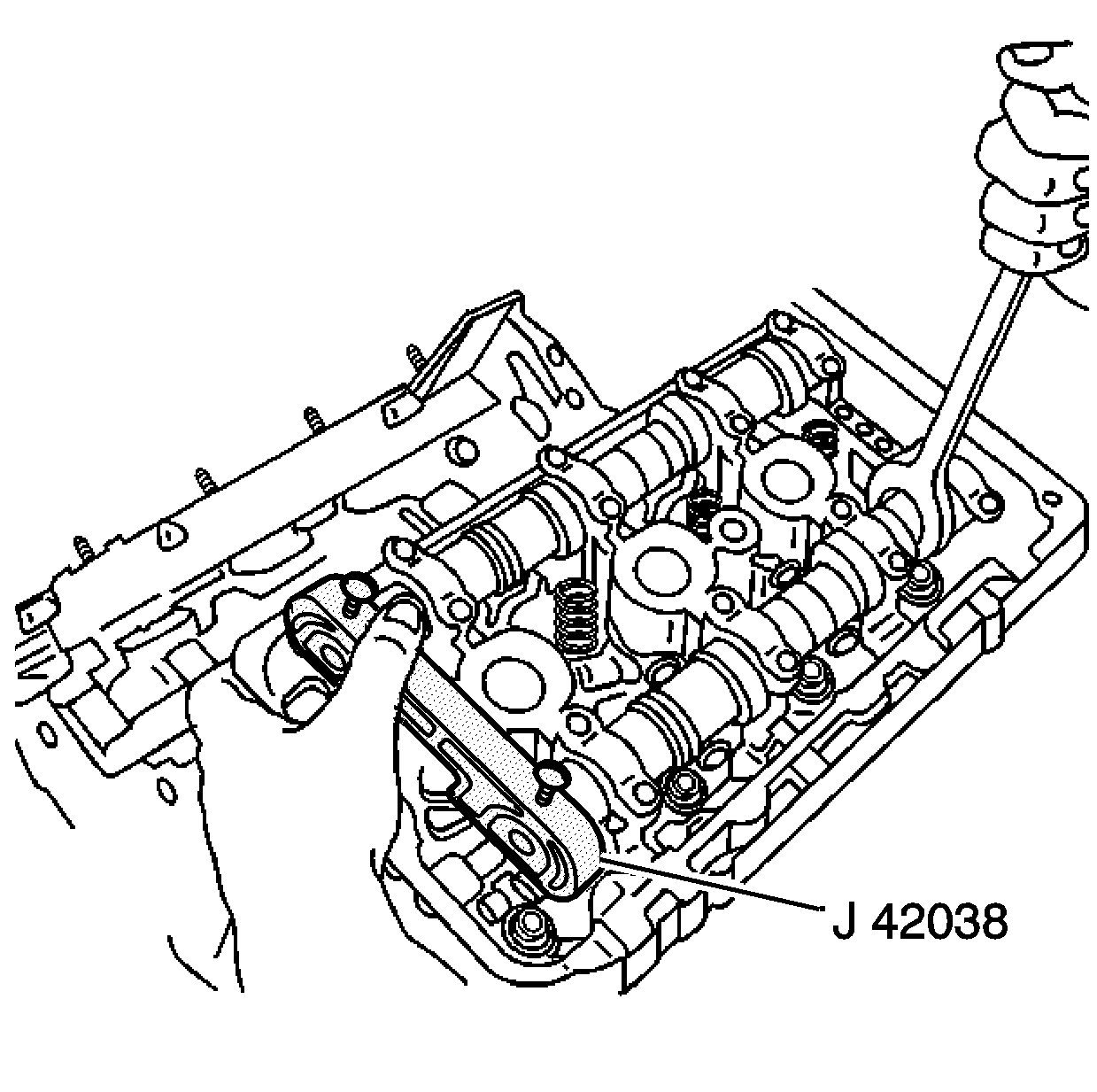
Important: You must install the J 42038 immediately after cam cover removal. The fixtures prevent unexpected camshaft rotation caused by valve spring pressure.
Installation Procedure
- If necessary, assemble the oil pump. Refer to Oil Pump Assemble .
- Align the crankshaft sprocket splines with the oil pump gerotor and install the sprocket in the oil pump.
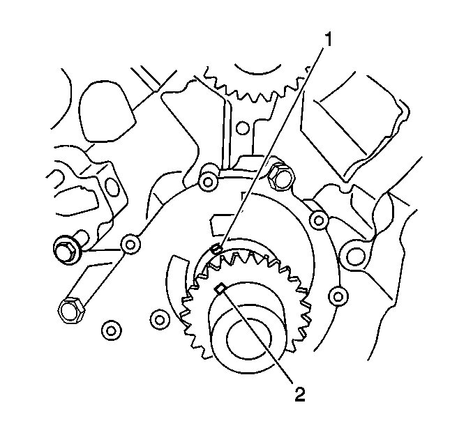
- Place the pump and sprocket assembly in position by rotating the crankshaft sprocket until the machined slot (2) is indexed with the drive pin (1) in the crankshaft.
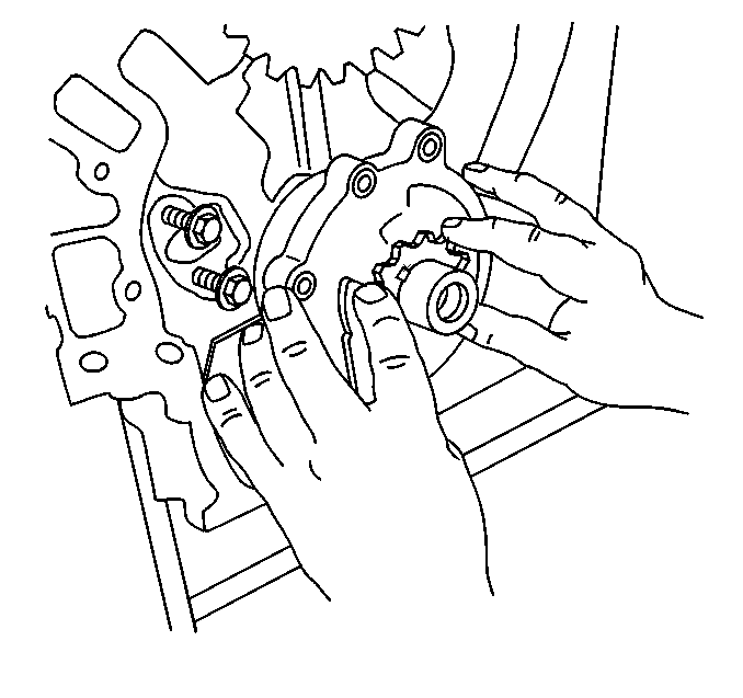
- Slide the pump and sprocket onto the crankshaft until a positive stop is felt. Make sure the crankshaft sprocket is aligned with the drive pin in the crankshaft.
- Install the oil pump pipe and screen. Refer to Oil Pump Suction Pipe and Screen Assembly Replacement .
- Install the oil pan. Refer to Oil Pan Replacement .
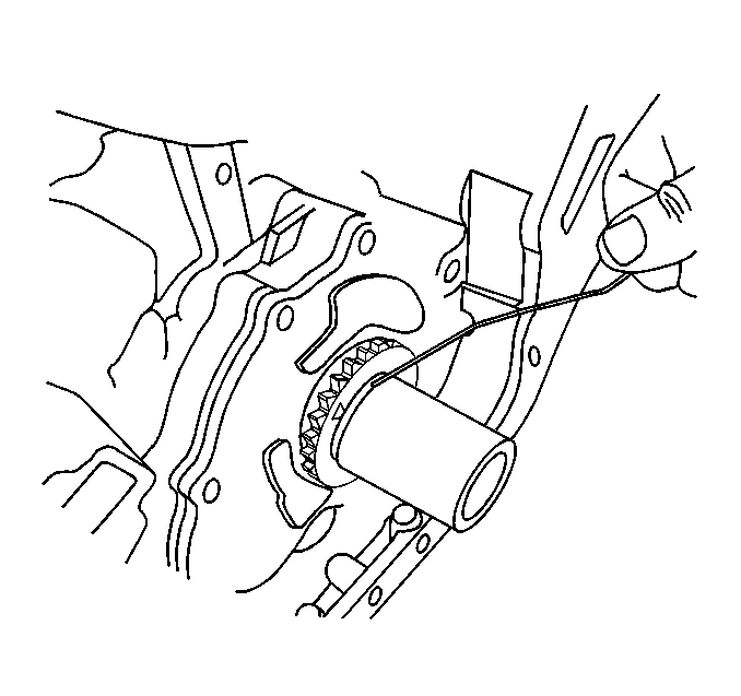
- When properly installed, the crankshaft sprocket will protrude from the oil pump but the face of the sprocket will be located behind the machined step in the crankshaft as shown.
- Align the pump body with the mounting holes in the cylinder block.
- Install the oil pump retaining bolts.
- Install the primary camshaft drive chain over the drive sprocket. Refer to Camshaft Drive Chain Tensioner Replacement .
- Install the camshaft drive chain tensioner (1).
- Remove the J 42038 from the cylinder heads.
- Install the camshaft covers. Refer to Camshaft Cover Replacement .
- Install the engine front cover. Refer to Engine Front Cover Replacement .

Tighten
Tighten the oil pump retaining bolts to 25 N·m (18 lb ft).

Important: Make sure correct primary and secondary camshaft drive chain timing are maintained.

