Removal Procedure
Tools Required
| • | J 38042 Dual O-Ring Joint Separator |
| • | J 39500-B A/C Refrigerant Recovery, Recycling, and Recharging (ACR4) System |
| • | J 39400 Electronic Halogen Leak Detector |
- Recover the refrigerant. Refer to Refrigerant Recovery and Recharging .
- Remove the cross car support brace. Refer to Cross Vehicle Brace Replacement in Body Front End.
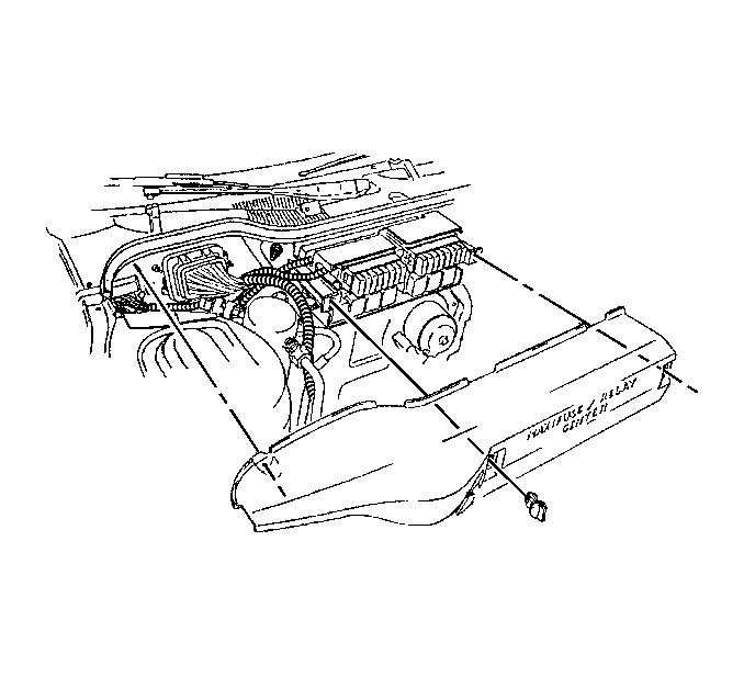
- Remove the fuse block cover.
- Remove the accumulator. Refer to Air Conditioning Accumulator Replacement .
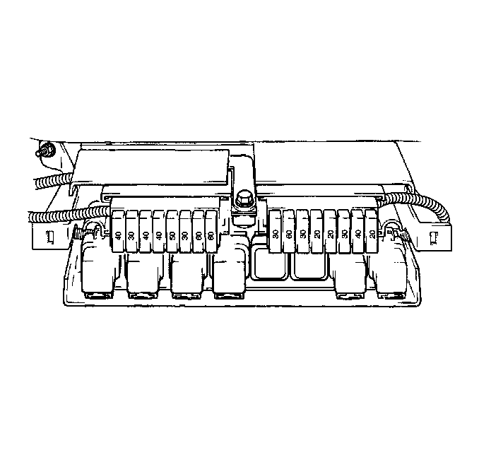
- Remove the positive booster cable from the multi-use relay center.
- Position the under hood fuse block out of the way.
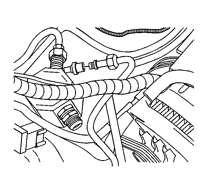
- Remove the evaporator tube from the evaporator.
- Remove the wire harness clip from the HVAC module.
- Remove the accumulator bracket.
- Remove the heat shield of the HVAC module.
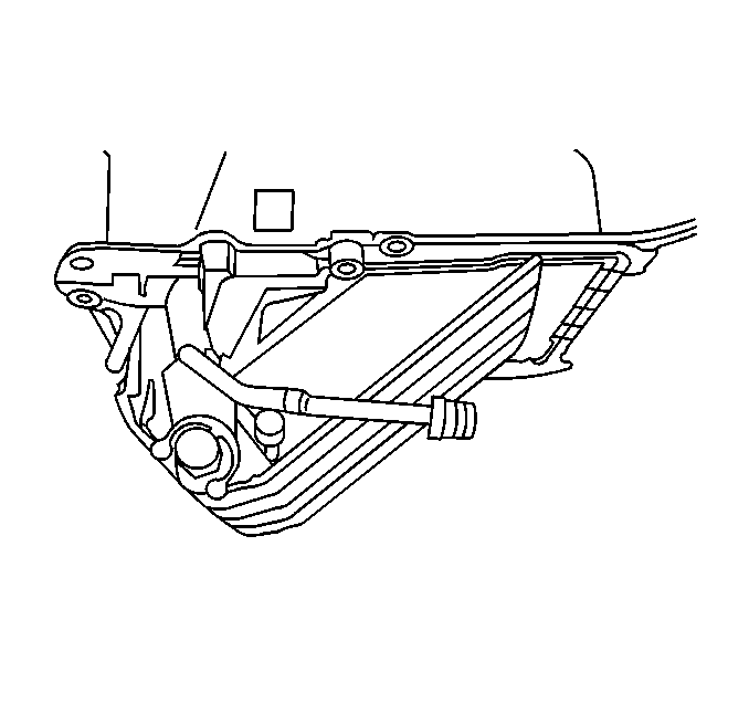
- Following the cut line, cut the top side of the HVAC module cover.
- Raise and support the vehicle. Refer to Lifting and Jacking the Vehicle in General Information.
- Following the cut line, cut the bottom side of the HVAC module cover.
- Lower the vehicle.
- Remove the fuel line clip from the HVAC module.
- Remove the insulator from the module.
- Remove the bolt that attaches the heater and A/C module assembly to the inside of the vehicle.
- Remove the evaporator core.
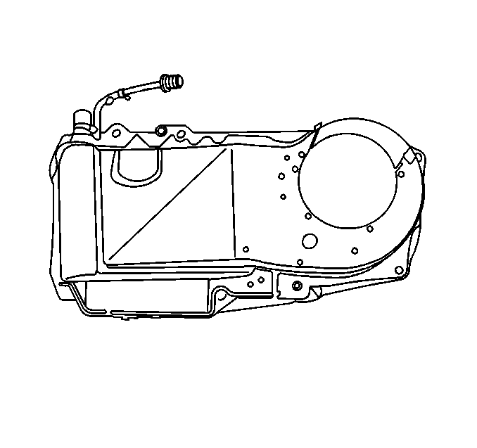
Remove the blower module from the HVAC module assembly.
Installation Procedure
- Install the evaporator core.
- Install the blower module to the HVAC module assembly.
- Install the bolts.
- Install the bolt to attach the heater and A/C module assembly to the inside of the vehicle.
- Install the insulator to the module.
- Install the fuel line clip to the HVAC module.
- Install the HVAC module heat shield.
- Install the bolts.
- Install the accumulator bracket.
- Install the screws.
- Install the wire harness clip to the HVAC module.
- Install the evaporator tube to the evaporator.
- Reposition the under hood fuse block to the original position.
- Install the booster cable from the multi-use relay center.
- Install the accumulator. Refer to Air Conditioning Accumulator Replacement .
- Install the fuse block cover.
- Install the cross car support. Refer to Cross Vehicle Brace Replacement in Body Front End.
- Recharge the A/C system. Refer to Refrigerant Recovery and Recharging .
- Leak test the system. Refer to Leak Testing .

Notice: Use the correct fastener in the correct location. Replacement fasteners must be the correct part number for that application. Fasteners requiring replacement or fasteners requiring the use of thread locking compound or sealant are identified in the service procedure. Do not use paints, lubricants, or corrosion inhibitors on fasteners or fastener joint surfaces unless specified. These coatings affect fastener torque and joint clamping force and may damage the fastener. Use the correct tightening sequence and specifications when installing fasteners in order to avoid damage to parts and systems.
Tighten
Tighten the bolts to 5 N·m (44 lb in).
Tighten
Tighten the bolt to 5 N·m (44 lb in).
Tighten
Tighten the bolts to 5 N·m (44 lb in).
Tighten
Tighten the screws to 6 N·m (53 lb in).

Tighten
Tighten the evaporator tube connection to 24 N·m (18 lb ft).

